The principle of operation and basic characteristics
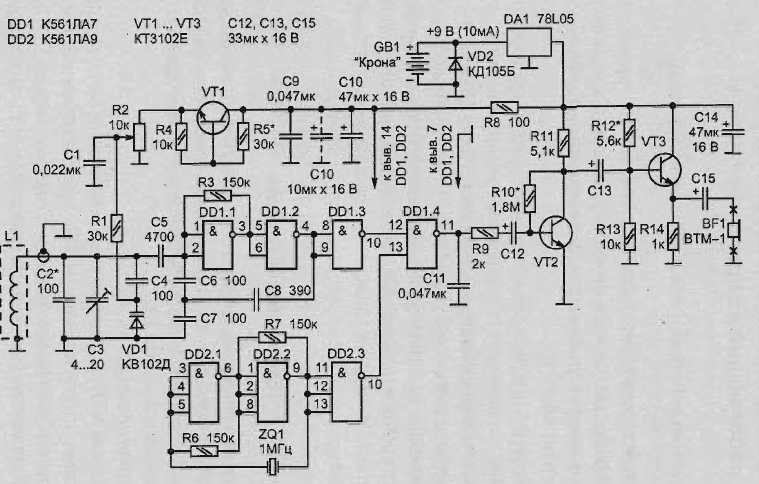
The detector (Fig. 2.28, (a) works on the principle of beating formed because the difference between the reference oscillation and search generators (5-10-th harmonic, selects the nearest frequency).
This allows to increase the sensitivity of the instrument to a high level that it becomes possible to detect:
- nickels in the soil at a depth of 10 cm;
- steel hatch cover or the pipe is at a depth of 65 cm.

Fig. 2.28. Schematic diagram unpretentious metal detector with high sensitivity working on the principle of beating
Running on available hardware components, the metal detector does not require careful settings and unpretentious in operation. Power supply - galvanic battery "Krona".
Schematic diagram
Search the generator is assembled by the so-called scheme "capacitive treatacne" logic elements DD1.1, DD1.2 IC CLA. Its oscillating circuit formed:
- search coil L1;
- capacitors C2-C4;
- the varicap VD1, control voltage which is supplied from the potentiometer R2, performing the function of the authority settings on low beat frequency.
The circuit further introduced the transistor VT1. Its purpose is to provide temperature compensation of the varicap VD1. If manufactured destined detector to work in favorable conditions, with small fluctuations in the ambient temperature, VT1 can be excluded from this device. The reference oscillator is based on two logical components 3I-NOT chip DD2 (CLA). Frequency stabilized by a quartz resonator ZQ1 (1 MHz).
And tunable, and the reference generator is available at cascade buffer (logic element DD1.3 and, accordingly, DD2.3) working on the mixer DD1.4. Generated in the mixer difference frequency signal is supplied to the amplifier (transistor VT2) with the emitter follower (VT3). The sound indicator detect metal in the ground serves as a microphone-earpiece BF1 from a hearing aid.
Voltage stabilizer DA1 5 provides In "electronics" food and semiconductor diode VD2 protects against incorrect polarity when connecting battery.
Configure the schema of the metal detector
Search generator need to "withdraw" on the desired frequency of 100-200 kHz, selecting capacitors C2, NW. With the average position of the slider of potentiometer R2 should be done to ensure that the greatest possible ratio of the frequencies of the reference and search generators get loud reproducible primer signal BF1 beating. Amplifier with emitter repeater to configure the selection of resistors R10 and R12. The benchmark should be the voltage of 2.5 V at the collector of VT2 and load resistor R14.
Adjustment temperature compensation performed on the transistor VT1, should be implemented the selection of resistor R5. Thus it is necessary to ensure that the voltage between the collector and emitter of VT1 was in the range of 2-2. 5 V.
The manufacture of the search coil
The search coil L1 is recommended to wind the ingot with a diameter of 160 mm. It should contain 60 turns of wire PEL-0,2. Then you need to produce single-layer the winding tape. After that, the coil should wrap (with a small depression between adjacent turns is a strip of aluminum foil for electrostatic shielding. Electrical contact between the ends of such a screen is invalid (otherwise it is a vicious spiral).
Received frame sensor still need to be wrapped to protect from damage two or three layers of electrical tape, to glue "epoxy" to the base of fiberglass (non-foiled!) a thickness of 2-4 mm. With bracket the device can be pristupiti to the carrier rod, for example, fiberglass ski a stick with a handle and a block.
Connection
In the case of the block you want to place a galvanic battery "Krona" and all "electronics", mounted on a printed circuit Board. Connection search coil tab - coaxial cable extending inside the support rod.
Element base
Now about the components necessary for Assembly of the detector. All of them, including semiconductor devices and circuits, you can choose from the category of inexpensive and widespread. In particular, fixed resistors type MLT-0,125.
As potentiometer R2 can be used by any compact, preferably the switch. Last on the circuit diagram conventionally not shown. The fixed capacitors C1, C9 and C11 can be any small, but with the values indicated on the circuit diagram.
More stringent requirements of the capacitors C2, C4-C8: for greater reliability and the longevity of their work in different conditions these capacitors, it is desirable to choose among thermostable. In particular, performing the role of "podstroechnik" capacitor Sz is preferably a ceramic, such as the most sustainable significant rapid temperature changes (for example, type CT-23 capacity 4-20 pF). And as C10, C12-C15, you can use a capacitor K53-2, guaranteeing stable operation of the scheme.
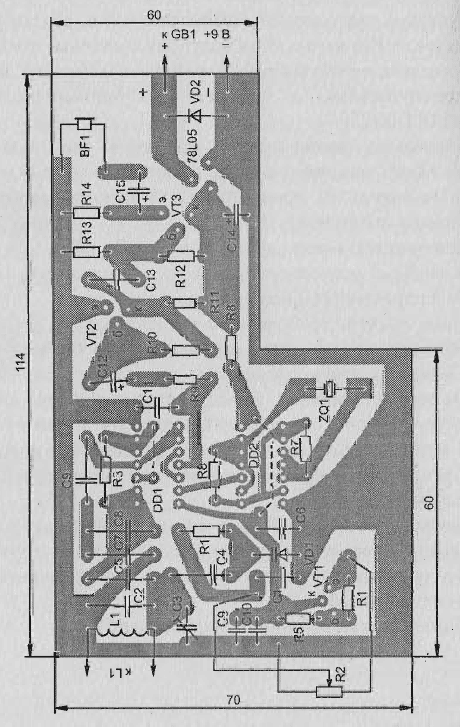
Sketch a circuit Board of a homemade metal detector is shown in Fig. 2.29.

Fig. 2.29. The printed circuit Board unpretentious metal detector with high sensitivity, operating on the principle of beating
Author: V. Grichko


