Schematic diagram
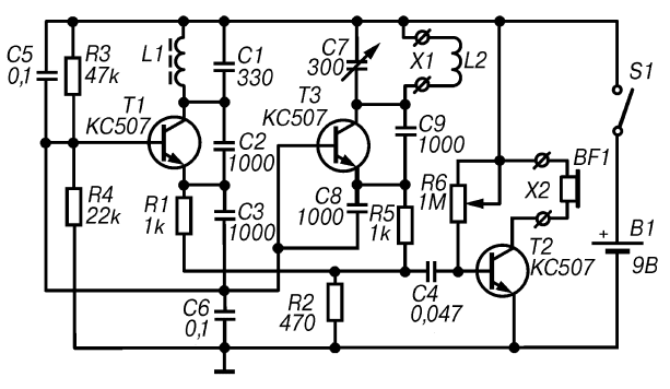
The proposed design (Fig. 2.1) represents one of numerous options of detectors type BFO (Beat Frequency Oscillator), that is is a device, based on the principle analysis of the beating occur when mixing two signals of close frequencies.

Fig. 2.1. A schematic diagram of a simple transistor detector
In the construction of apparatus used two simple LC-oscillator is made on the transistors T1 and T3. Operating frequency of these generators is determined by the parameters circuits included in the collector circuit of the respective transistors. Contour the first generator, which is the reference, is formed by the capacitor C1 with a capacity of 330 pF and the coil L1. In the second circuit, measuring, generator used variable capacitor C7 with a maximum capacity of 300 pF and the search coil L2.
The outputs of the generators through resistors R1, R5 and a capacitor C4 is connected to the base the transistor T2, which amplifies the signal of the beat frequency. With collector transistor T2, the amplified signal is fed to the headphones BF1. Level the volume of this signal is controlled by the variable resistor R6.
Since the operating frequencies of the generators are in the medium wave band, their the signals in the phones cannot be heard. When it is possible to achieve precise settings for each generator to the same frequency, the audio signal in the phones will also be be absent. If using a capacitor C7 to set the measuring generator on almost the same frequency as the reference oscillator, the phones will be audible signal beat frequency. In the absence in the area of the search coil L2 metal objects operating frequency of the measuring oscillator remains unchanged, so the same will be the beat frequency. In this mode you can the frequency deviation can be caused only by the unstable work of both generators.
With the appearance in the area of the search coil L2 of a metal object, the resonant frequency of the circuit L2C7 will change. This will change the working the frequency of the measuring oscillator and, as a consequence, the frequency of the beat signal. These changes serve as a source of information about metal detecting subject.
The power of a simple transistor detector is from the source B1 a voltage of 9 V.
Details and design
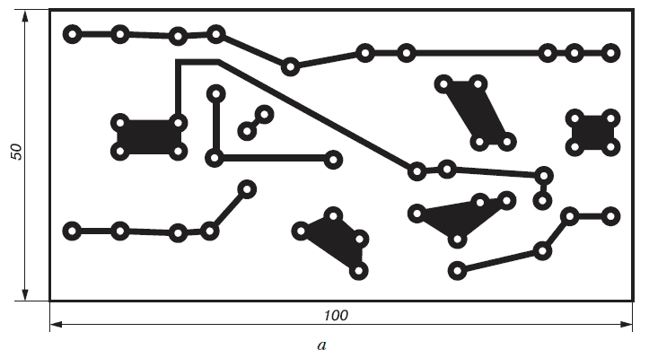
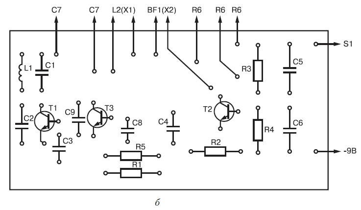
All the details of a simple transistor detector, except search coil L2, capacitor C7, resistor R6, connectors X1 and x2 and switch S1, are on the PCB size 100x50 mm (Fig. 2.2), made of sided glass Micarta or PCB.
To detail used in this device without facing any special requirements. Naturally, it is recommended to use any small capacitors and resistors, which easily can be placed on printed Board.
Coil L1 of the reference oscillator wound wire PEL diameter 0.1-0.2 mm on core with a diameter of 8 mm and contains 100 turns. The coil L1 can be wound on the ferrite core or paper tube without core. As capacitor C7 you can use any variable capacitor with air dielectric with a maximum capacitance of about 300 pF, for example the capacitor from any old radio.


Fig. 2.2. Printed circuit Board (a) and the arrangement of elements (b) simple transistor detector
Printed circuit Board with the controls it contains and the power source are placed in any appropriate plastic or wooden case. On the housing cover set the capacitor C7, the volume control R6 switch S1, and the connectors X1 and x2 for connecting respectively the search coil L2 head phones and BF1.
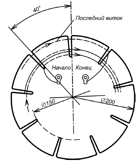
For making search coil L2 (Fig. 2.3) you will need to cut a circle 100 mm diameter made of plywood or other material (Micarta, textolite) thickness 1.5-2.5 mm. the Circle should be divided into sectors with an angle of 40° and in these places to cut to the center at a distance of 20 mm from the edge. In the slot will go wire diameter 0.2-0.3 mm (e.g. brand PEL) and turn to turn to reel 30 turns. To so made a search coil attached convenient pen. The connection of the coil L2 to the circuit Board is carried out through small-sized connector.

Fig. 2.3. The design of the search coil L2
As the power source B1 can be used, for example, the battery "Krona" or two batteries 3336L connected in series.
Establishing
When using non-defective parts correctly assembled the detector starts to work almost immediately. Calibration should be carried out in conditions when metal objects are removed from the search coil L2 at a distance of not less than 1,5 m.
Since in this section we are talking about simple design, the phones at first turn will be heard from the different harmonics. Therefore, tuning the device, you should choose the strongest signal using a capacitor C7 and adjust the volume controller R6. The choice of the most strong harmonics can be done by ear or using an oscilloscope or frequency counter.
The process of setting up a simple transistor detector ends.
The order of work
In the practical use of the considered detector should capacitor C7 to perform additional tuning to the strongest signal harmonics and adjust the volume using the controller R6.
Now if in range of the search coil L2 will be any metal object, the pitch will change. When approaching one metals the frequency of the beat signal will increase, and when approaching others will decrease. To change the tone of the beat signal, having some experience, you can easily determine the kind of metal, magnetic or non-magnetic, made detected object.
Author: M. V. Adamenko


