


")

The principle of operation of this detector is to record the signal reflected a metal object. This signal arises from action on the metal of the alternating magnetic field of the transmitting (radiating) coil.
Take-up spool is located in one plane with the transmission in such a way that through magnetic lines of force generate a small EMF. On the findings receiver coil signal is absent or very small.
Additional reduction of this signal provides the compensation node. But if field coils hits a metal object, inductive coupling between coils changes on the conclusions of the receive coil appears an electrical signal which amplified, rectified, and then filtered.
In the end, the filter you receive a constant voltage, increasing when approaching the coils of a metal object. This voltage is supplied to one input of a comparison site, which compares with the reference voltage, which is applied to its second input. The level of the reference voltage is adjusted so that even small the amplification of the signal leads to a significant change in the level of the signal at the output node comparison.
This, in turn, actuates an electronic key, sound Manager alarm detection of a metal object.
Schematic diagram
Diagram of the detector shown in Fig. 2.2. Generator configured to the VT2 transistor and circuit L1C3, operates at a frequency of about 4.6 kHz.
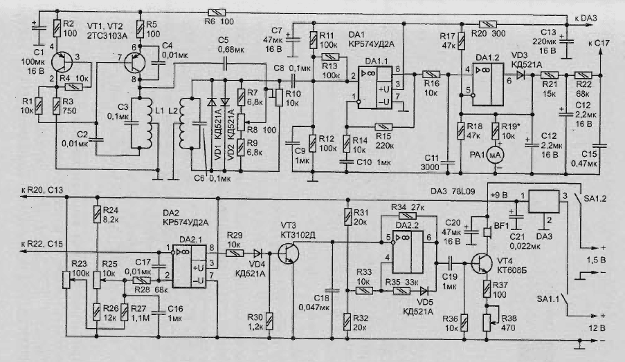
Fig. 2.2. A circuit diagram (click to enlarge)
Low the frequency generator provides:
- on the one hand, the weak response of the detector to unwanted signals (for example, resulting from the wet sand, small pieces of metal, etc);
- another good sensitivity.
Depth of detection of objects by any detector depends on the working frequency signal, its power, size of the inductors, as well as the size and shape of the object and its position.
The higher the frequency, the shallower the depth of detection of small objects. The larger the inductance, the greater depth of detection. The transistor oscillator is assembled on the Assembly TSA. Transistor VT2 works directly in the generator, and the transistor VT1 in conjunction with the divider of the details R2…R4 - in the heat stabilizer that provides temperature compensation.
The signals to the receiving coil L2, are limited in amplitude (in case of detection of a large metal object) diodes VD1, VD2, and then amplified by the operational amplifier DA1.1. The input of this chip through a capacitor C5, resistors R7-R10 and capacitor C8 a signal compensation of the generator. It weakens it by stepping on the coil L3 signal from the coil L1 in the absence of near metal objects.
After amplification, the signal passes through the filter R16C11 at the shelter DA1.2. When the positive input of the voltage received at the non-inverted input IC, diode VD3 is open and provides negative feedback. The capacitor C12 is charged, and the indicator hand RA1 is rejected.
When a negative input voltage the diode is closed, there is no feedback at the cathode diode zero volts.
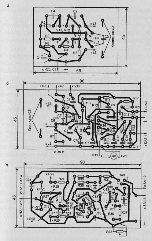
Fig. 2.3. The appearance of three printed circuit boards the metal detector circuit is 4.6 kHz
The signal from the detector is smoothed by the filter R21C14R22C15 and is supplied to the comparator DA2.1, where it is compared with a reference voltage, an adjustable variable resistors R23 (roughly) and R25 (exactly).
Upon actuation of the comparator the voltage at the output is reduced, the transistor VT3 is closed, and starts to operate the tone generator, assembled on OU DA2.2.
Its output signal is fed to the power amplifier is performed on the transistor VT4, the load of which is a head phone from the hearing aid. The volume sound adjust variable resistor R38. The output stage is powered from a separate source, which eliminates the possibility the excitation device. The main part of the circuit of the metal detector is powered by the source voltage of 12 V, which is additionally stabilized by chip DA3 at 9 V.
Details of the detector are mounted on three printed circuit boards (Fig. 2.3 (a) of one-sided foil fiberglass. They are designed for use resistors MLT-0,125, resistor JS4-1 (R10) capacitors K71-7 (NW, C6). Dial indicator PA1 - level indicator recording of any tape recorder.
The coils of
Special attention should be paid to the manufacture of coils. This will determine the quality operation of the metal detector in the future. The coil is optimally wound on a mandrel with a diameter of 140 mm, which well use a glass jar.
Each coil shall consist of 200 turns of enameled copper wire with a diameter of 0.27 mm with a branch from the secondary thread. Before removing the coil mandrel, it should be dressed and three or four different places, and after removing the wrap durable thread that coils tightly to each other.
Further, the coils must be given the shape shown PA Fig. 2.4, and attach them to a plastic plate 1 thread 2. Transmission coil 3 are fitted at the bottom, and reception room 4 - upstairs. Receiving coil shall be fitted with aluminum (foil strips) screen a gap that prevents the formation of a closed loop.
The findings of the coils need to connect with the rest of the instrument cable shielded braid. The distance between the vertical (Fig. 2.4) turns coils should be equal to approximately 25 mm. Finally clarified after it adjust the metal detector on the minimum indicator reading when RA1 the absence of coils near metal objects.
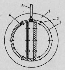
Fig. 2.4. The shape of the coil
After final fixing of the coils with glue or sealant can cover the top decorative housing and secured to him the post.
Setup and operation
Setup of the detector is to install the engine resistor R10 (in the middle position of the slider of resistor R48) to such an arrow indicator PA1 was on the "zero" mark. For convenience of operation of the device is desirable to set the arrow in the middle scale selection resistor R19. To do this in some cases will have to change connecting the findings of one of the coils of the generator.
During operation of the metal detector after 20 minutes of setting the operating mode resistor R8 should be to achieve "zero" the dial indicator. After that, variable resistors R25 and R23 should install support the voltage close to the triggering of the comparator and the emergence of tonal sound.
Author: V. Grichko