Schematic diagram
As already mentioned, the considered metal detector is one of numerous variants of the device type BFO (Beat Frequency Oscillator), that is is a device, based on the principle analysis of beating the two frequencies. In this structure, the change in frequency is carried out on hearing.

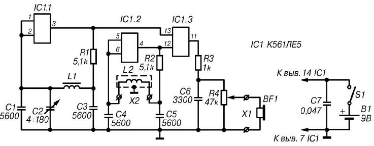
Fig. 3.4. Schematic diagram of the detector on the chip CLE
The basis of the scheme of this device are measuring and reference generators, mixer scheme and acoustic indication (Fig. 3.4). Reference and measurement the generators are made on the elements of the chip IC1.
Reference oscillator assembled on the element IC1.1. Negative feedback direct current between the output (pin 3) and the input (pins 1, 2) for this element through the resistor R1 and an inductor L1. The parameters of the coil L1 and resistor R1 is chosen so that the element operates in the linear range transfer characteristics. Thus, the conditions for excitation cascade at a frequency of about 100 kHz, which is determined by the parameters of the elements contour L1C1C2C3. Element IC1.1 has a high input impedance, so the factor of the circuit and the stability of the oscillator frequency is relatively high. Resistor R3 weakens the shunting effect of the output resistance of the element on circuit. If necessary, the oscillation frequency of the reference oscillator can be changed in a small range of the variable capacitor C2.
The measuring generator is made in a similar way to the element IC1.2. When operating frequency of this oscillator is determined by the parameters of the elements contour L2C4С5. Coil L2 is a search. When approaching search coil L2 tunable oscillating circuit of the generator to a metal object its inductance is changed, which causes a change in the operating frequency of the generator.
Fluctuations from the reference and test oscillators arrive at the inputs of the element IC1.3, performing the functions of the mixer signals. As a result, the output element IC1.3 will be present not only from the fundamental frequency of the generators, but signals harmonic components of the difference and sum frequencies. One of the most powerful will be the signal of the difference frequency, which is allocated to the resistor R4. Other signals are suppressed by the filter composed of resistor R3 and the capacitor C6.
The output signal via the volume control R4 is applied directly to the head phones BF1. Use additional low-frequency amplifier is not required because the amplitude of the output signal of the element IC1.3 is several volts.
Power to the chip IC1 is supplied from the source B1 voltage of 9 V.
Details and design
For the manufacture of the considered detector, you can use any the breadboard. So used to detail without facing any limitations associated with dimensions.

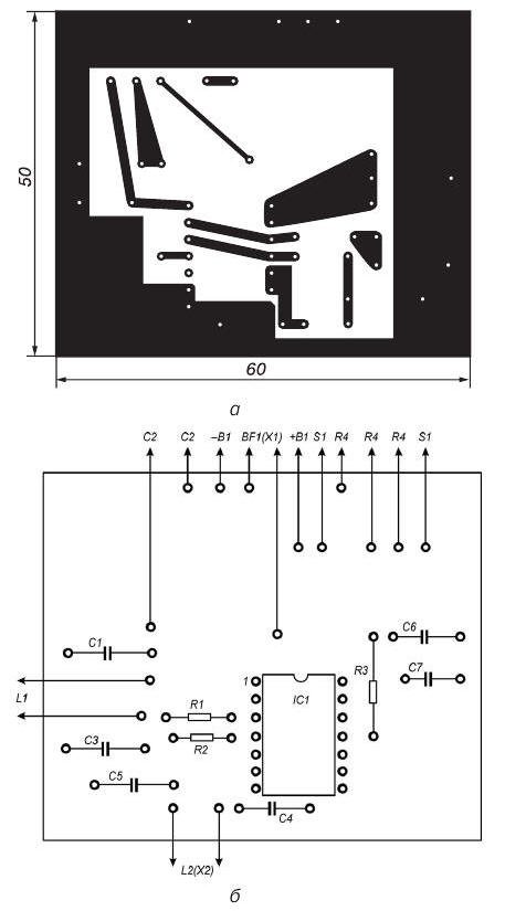
Fig. 3.5. Printed circuit Board (a) and the arrangement of elements (b) of the metal detector on a chip CLE
The details of this detector is recommended to be placed (with the exception of the search coil L2, a resistor R4, connector X1 and S1) on the PCB size h mm (Fig. 3.5), made of one-way foil Micarta or phenolic resin. Unused input the findings of the fourth element of the chip IC1 is necessary to connect with the common wire. In this device, you can use the IC series C, K, K, containing at least three logical element "or not" or "and - not", for example type CLE, CLE, CLE or CLE.
As the capacitor C2 is recommended to use any capacitor variable capacity from small-sized radio. The maximum capacity of this the capacitor should not be less than 150 pF. The remaining capacitors can be any miniature ceramic, for example of the type KLS, km or CT. Need to note that to increase the thermal stability of the device, the capacitors C1, C3-C5 must have TKE no worse M or M1500. Fixed resistors can be arbitrary small, such as type MLT-0,125. Variable resistor R4 may have a resistance of from 10 to 68 ohms. In as such a regulator is not recommended to use resistors, mechanical connected to the power switch S1.
Coil L1 of the reference oscillator circuit may be formed on the frame from coil of the inverter circuit of any small-sized transistor radio. This coil is wound on the three-section frame the inverter circuit of the radio Sokol-403". In this case, the coil L1 is placed in the armor the core diameter of 8.6 mm ferrite NN with podstroechnik diameter of 2.8 and length of 12 mm made of the same ferrite. Coil L1 contains 200 turns of wire sew-2 with a diameter of 0.09 mm.
For making search coil L2, it is recommended to use a piece of copper or aluminum tube with an internal diameter of 6-8 mm and a length of about 950 mm. Inside the tube should be pulled the harness of 18 pigtails MGTF diameter of 0.07 mm pre-stretched in a PVC pipe. Dural tube with her wires should be bent on a template in a ring with a diameter of about 300 mm End of the wire, which is the beginning of the first coil should be soldered to the proper terminal of the capacitor C4, the beginning of the second round by the end of the first coil and so on. The end of the last coil is soldered to the corresponding output capacitor C5. The result is a coil that contains 18 of turns and having inductance of about 350 micrograms.
In the manufacture of the coil L2, it is necessary to ensure that did not happen circuit ends of the shielding tube, as in this case, is formed closed loop.
Instead of thin-walled tubes for the manufacture of the screen you can use regular the aluminum foil. In this case, the additional rigidity of the coil L2 can be given, if to place it between the two discs of plywood or Micarta appropriate sizes.
As a source of audio signals, you should use a high-resistance head phones with possibly a high resistance (about 2000 Ohms). Is suitable, for example, widely known phones TA-4 or TONE-2. When using low impedance phones the metal detector should complement cascade transistor KT315B, setting the resistor R3 has a resistance of 10 ohms, and the capacitor C6 is the capacitance of 1000 pF.
As the power source B1 can be used, for example, the battery "Krona" or two batteries type 3336L connected in series.
Printed circuit Board with the controls it contains and the power source are placed in any suitable metal enclosure. On the housing cover installed variable resistor R4, connector X1 for connection of headphones BF1, connector X2 for connecting the search coil L2 and the switch S1.
Establishing
As with the adjustment of other detectors, the establishment of this unit should be carried out in conditions when metal objects are removed from the search coil L2 at a distance of not less than one meter.
You must first configure the operating frequency of the reference oscillator. For this initially, the reference oscillator frequency is set equal to the operating frequency measurement of the generator by adjusting the position of the trimpot the core of the coil L1 to a complete loss of sound in head phones, it has zero beat. Pre-rotor capacitor C2 should be set approximately to the middle position. As a result with a slight turn of the handle of the capacitor C2 in any direction in phones you should see the sound low tone. If necessary to adjust the frequency the reference oscillator can use a frequency counter or an oscilloscope.
The recommended frequency difference between the reference and measurement generators needs to make 400-500 Hz. The frequency of the reference oscillator needs to be above the frequency of the measuring oscillator. The choice of such high values of differential frequency is explained by the fact that both of the generator, the reference and measurement made on the same General crystal chips, and so between them is inevitable arise parasitic coupling, to eliminate almost impossible. This fact and forces one to use in this detector the beating frequency of 100-300 more Hz, which inevitably reduces its sensitivity.
The order of work
With error-free installation, defective parts and correct adjustment consider the detector is ready for use immediately after the configuration. Before you start prospecting the capacitor C2 is desirable to set possible a lower beat frequency. This will increase the sensitivity of the device, as to ensure the registration of even small changes in the frequency of measuring generator. However, the very low beat frequency cannot be selected, because the volume of the sound in the phones will drop sharply.
If in the process, the frequency of the signal to the head phones will change it indicates the presence in the area of the search coil L2 of any metal object. When approaching the coil to the subjects of the magnetic metals (such as iron, ferrite or Nickel) the frequency of the beat signal will be to increase, and when approaching the objects from non-magnetic metals (e.g. from aluminum, copper or brass) will decrease. To change the tone of the beat signal, having some experience, you can easily determine the kind of metal, magnetic or non-magnetic, made the detected object.
The volume level of the signal in headphones adjustable resistor R4.
Author: I. Nechaev


