The appointment and functions
This device helps to detect large metal objects at depths of up to 0,8 m. It is often necessary to builders, employees of gas service and utilities for finding pipes, manholes and manhole covers That was under a layer of asphalt, earth or snow.
The principle of operation
The principle of operation is based on measuring the beating of the two frequencies received from reference and search generators. When approaching the scope of the search coil generator to large metal objects, its inductance changes, and with it varies and the frequency of the search oscillator. As a result changes and frequency beat in the headphones.
The device is powered by battery "Krona", consuming current of 5-8 mA.
Schematic diagram
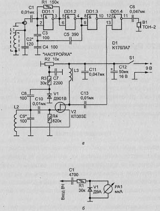
Schematic diagram of the detector shown in Fig. 2.33, and.

Fig. 2.33. A simple metal detector: (a) schematic diagram; b - schematic generator circuit-tester
Search the generator is assembled by the so-called scheme "capacitive treatacne" the elements of D1.1 and D1.2. Its frequency is defined by the elements of the circuit L1C2. On the element D1.3 chip assembled buffer amp, an element of D1.serves 4 mixer. Reference oscillator constructed according to the scheme of inductive treatacne field the transistor V2 series CP. Its frequency depends on the values of the coils L2 and capacitor C9, and the capacitance of the varactors V1. The load is the coil L2.
Coil
Coil L1 consists of 100 turns of wire sew-2 0,27 wound on the ring with a diameter of 250 mm, made of vinyl plastic tube with a diameter of 16 mm. The winding is wrapped with a layer of aluminum foil with a gap between the beginning and the end of 4-6 mm, not formed a closed loop. The foil is connected to the "minus" the output of the coil.
Coil L2 consists of 150 turns of wire PELSHO 0,14 wound on the ring K8 x 6 x 2 ferrite brand N. The allotment is made-thirds of turns counted from grounded output. On the same ring wound coil L3, the same wire to fill.
Coil L3 serves as a load device.
The design of the device
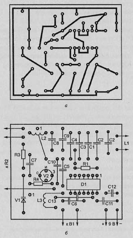
The device is mounted on a circuit Board from one-sided foil fiberglass 1.5 mm thick, a size of 55 x 65 mm (Fig. 2.34 a).

Fig. 2.34. A simple metal detector: a circuit Board; b - location elements
Components and recommended replacements
The device uses resistors - MLT-0,25, MLT-D with the deviation of ±20%. Capacitors C2-C5, C8, C9 - CM-4B, C12 - C50-6, others - K10-7V. The varicap V1 - any of a series of D.
Instead of the transistor CPE you can apply the same with any other letter index.
The arrangement of the elements
The location of parts on the motherboard shown in Fig. 2.34 b.
Adjustment of the metal detector
The establishment of the unit is to verify the functionality of the two generators when means of a wavemeter or oscilloscope. Optionally, selecting the capacitance C2 can to configure the circuit L1C2 at a frequency of 100 kHz. With the help of the capacitor C9, the frequency of the reference oscillator can also be configured to 100 kHz with an average position of the slider of the resistor R2. The headphones should to be heard the whistle, published by beating.
If not wavemeter, the presence of HF oscillations can see and with a simple the probe (its scheme is shown in Fig. 2.33 b).
If the generators are working, when connecting the probe to the terminals 12 and 13 of D1.4 the meter needle will be deflected by a certain amount depending on his sensitivity.
Author: R. Ceteris


