No doubt, many novice hobbyists interested in design simple metal detector, the basis for which was the scheme, repeatedly published in domestic and foreign specialized publications in the mid 70-ies of the last century. With this metal detector only two transistors, it is possible to detect metal the subjects removed from the search coil at a few tens of centimeters.
Schematic diagram
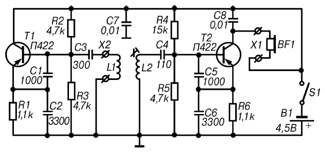
This design represents one of the variants of type detectors FM (Frequency Meter), that is, a device, based on the principle of measuring the frequency deviation of the reference oscillator under the influence metal objects caught in the area of the search coil. In this case assessment of change of frequency is done by ear (Fig. 2.4).

Fig. 2.4. A schematic diagram of a simple metal detector on two transistors
The basis of the scheme of the device comprise a high-frequency generator and a receiver that registers the change of the oscillator frequency when approaching metal subjects.
A high-frequency generator is assembled on the transistor T1 according to the scheme of capacitive treatacne. The oscillating circuit of the reference oscillator consists of a chain of sequentially included capacitors C1, C2 and C3 which are connected to the coil L1. Operating frequency The RF generator is determined by the inductance of this coil, which at the same time is a search coil.
One of the features of this device can be considered that as analyzer it uses a heterodyne type receiver, which is made only one transistor. In this case, the cascade transistor T2 combines the functions local oscillator and detector. The local oscillator is built on a capacitive treatacne. The advantage of this scheme is the possibility of using coils inductance without derivation, albeit slightly, but simplifies the design. The oscillatory circuit of the oscillator includes an inductor L2 and the capacitance composed of series-connected capacitors C4, C5 and C6. The frequency the local oscillator can be changed by turning the trimpot core of the coil L2.
With the collector of transistor T2 proyektirovanii signal is supplied to the head phones BF1.
If near the coil L1 will be a metal object, then its inductance will change. This will result in a change of frequency of the reference generator, that will immediately registered by the receiver of the detector. As a result, the tone signal in phones BF1 will change.
Details and design
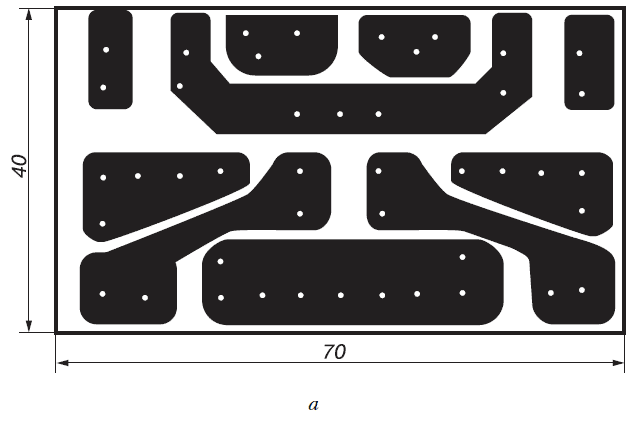
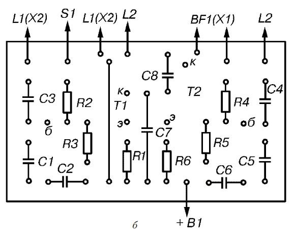
All the details of a simple metal detector on two transistors except the search coil L1, coil lo L2, connector X1 switch S1 and located on the PCB size h mm (Fig. 2.5), made of sided glass Micarta or PCB.
To detail used in this device without facing any special requirements. It is advisable to use any small-sized capacitors and resistors that can be placed on the circuit Board. As can be seen from concepts, in this detector uses outdated RF transistors type P, P401 or P. Instead, you can use any modern RF conductivity transistors p-n-p is designed to operate in input cascades radios.
The search coil L1 used in the reference generator is a rectangular frame size h mm, 32 which is wound a coil of wire PEV-2 in diameter of 0.35 mm or, for example, pelsho diameter of 0.37 mm.
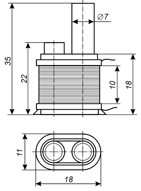
In two cylindrical paper frames placed segments of the ferrite rod type with permeability of 400 or N diameter of 7 mm. in Length to the first, fixed constantly, is about 20-22 mm. the Second rod is movable and is used to adjust the inductance of the coil. Its length is 35-40 mm. Frames rods wrapped with a paper tape, which are wound with 55 turns of wire Pelsho diameter of 0.2 mm. you can Also use wire type sew-1 sew-2.
Coil L2 (Fig. 2.6) should be installed at a distance of 5-7 mm from the plane the location of the turns of the coil L1.
As a source of audio signals can be used with head phones resistance 800-1200 Ohms. Suitable and widely known phones TONE-1 or TONE-2, however, when applying both the primer you need to include and not sequentially in parallel, that is, to connect the primer plus one to plus another, and minus - to minus. The total resistance of phones should be about 1000 Ohm.


Fig. 2.5. Printed circuit Board (a) and the arrangement of elements (b) simple metal detector on two transistors
The power of a simple metal detector on two transistors is supplied from source B1 voltage of 4.5 V. as such a source can be used for example, the so-called square battery type 3336L or three element type 316, 343, connected in series.
Printed circuit Board with the controls it contains and the power source are placed in any appropriate plastic or wooden case. On the housing cover set the switch S1 and the connector X1 for connection of headphones BF1.
Coils L1 and L2 are connected to the dress flexible stranded insulated wire.
Establishing
The setting of the metal detector should be carried out under conditions where the metal items removed from the search coil L1 at a distance of not less than 1.5 m.

Fig. 2.6. Coil design L2
After power on, you should check the voltage at the emitters of the transistors. The emitter of transistor T1 must be the voltage of -2.1 In, and on the emitter the transistor T2 is about -1 V.
Next, slowly moving the trimpot core of the coil L2, it is necessary to achieve the emergence of phones in a loud clean signal of low frequency. If initially, the generator is configured, for example, on the frequency of 465 kHz, phones to listen to the signal frequency of about 500 Hz.
When approaching the coil L1 to a metal object, which in the configuration process can be used, for example, tin, tone sound low-frequency signal to the head phones will change. Beginning changes in the tone signal must be at least approximately to fix. After do this by moving the core of the coil L2 for a more accurate tuning of frequency lo, it is necessary to achieve the greatest sensitivity of the device.
The process of setting up a simple metal detector on two transistors ends.
The order of work
The search operations with the help of this device does not have any features. If in range of the search coil L1 will be metal the subject, the height of the tone in the head phones will change. When approaching one metals the frequency of the signal will increase, and when approaching others be reduced. To change the tone of the beat signal, having some experience, you can it is easy to determine the kind of metal, color, or so-called black, made detected object.
Author: M. V. Adamenko


