The principle of operation
As the transmitter used a multivibrator, and as receiver - the audio frequency amplifier. The first of these devices and the input of the second connected identical in size and winding coil data.
For the system of such transmitter and receiver became the detector, it is necessary to arrange coils so that in the absence of extraneous metal items the connection between them was practically absent, i.e., the signal transmitter goes directly into the receiver.
As is known, the inductive coupling between the coils is minimal, if their axis vzaimnoperpendikulyarnykh. Therefore, if the coil of the transmitter and receiver positioning, the signal transmitter in the receiver not to listen will.
When you receive close to this balanced system metal subject therein under the action of an alternating magnetic field of the transmitting coil there are so-called "eddy currents" and, as a consequence, the self-magnetic field, which induces in the receiving coil a variable EMF. The signal, adopted the receiver converts the phone into sound. Its volume depends on the size of the object and distance to it.
Specifications
Technical characteristics of the detector are the following:
- the operating frequency is about 2 kHz;
- depth of detection:
- the coins diameter 25 mm to about 10 cm;
- iron and aluminum sealing caps, respectively, 20 and 25 cm;
- steel and aluminum plates with dimensions 200 x 300 mm - 40 and 45 cm;
- a manhole cover is 60 cm.
A schematic diagram of a transmitter
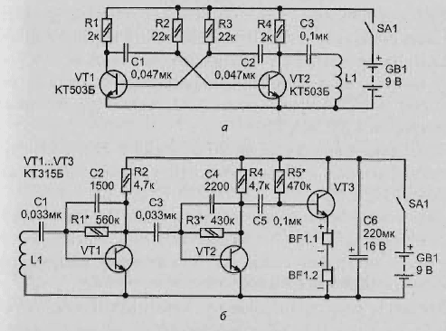
Diagram of the transmitter shown in Fig. 2.13, and. It is a symmetrical multivibrator to transistors VT1, VT2. The frequency of the generated oscillations is determined by the capacity capacitors C1, C2 and the resistance of resistors R2, R3.
The audio signal from the collector load of the transistor VT2 - resistor R4 - through the coupling capacitor Sz is supplied to the coil L1, which converts electrical oscillations in an alternating magnetic field.
Schematic diagram of the receiver
The receiver is a three-stage amplifier of sound frequency made according to the scheme shown in Fig. 2.13, b. The input included the same coil L1, as in the transmitter. The amplifier output is loaded are connected in series phones BF1.

Fig. 2.13. Schematic diagram: a transmitter; receiver
Operation of the detector of the power scheme
The alternating magnetic field of the transmitter, the induced coil in a metal the subject acts on the coil receiver. As a result, it occurs the electric current has a frequency of about 2 kHz. Through the coupling capacitor C1, the signal is input to the first stage the power, of the transistor VT1. The amplified signal with its load - resistor R2 is fed through coupling capacitor C3 to the input of the second cascade, assembled on the transistor VT2.
The signal from its collector through a capacitor C5 to the input of the third stage - the emitter follower transistor VT3. It amplifies the current signal and allows you to connect the load low impedance phones. To reduce the effect of ambient temperature on the stability of amplifier, first and second cascades introduced negative feedback DC voltage start-up: a resistor R1 between the collector and base VT1 transistor; a resistor R3 between the collector and the base of VT2.
The gain reduction at frequencies below 2 kHz achieved an appropriate choice the separation capacity of the capacitors C1, NW. The gain reduction at frequencies above 2 kHz - introduction to first and second cascades a frequency dependent negative feedback DC voltage via capacitors C2 and C4.
These measures allowed to increase the immunity of the receiver. The Capacitor C6 prevents the excitation of the amplifier when an increase in internal resistance the battery as it discharges.
Recommendations for the production of coils
The coil of the receiver and transmitter are the same. To make them by following way. At the corners of a rectangle of dimensions 115 x 75 mm Board to drive four nail: diameter 2-2. 5 mm; length of 50-60 mm. Pre-need to put on nails polyvinylchloride or polyethylene pipes with a length of 30-40 mm. This will give sufficient insulation of the whole structure.
Isolated thus nails need to be wound with 300 turns of wire sew-2 with a diameter of 0.12-0.14 mm. Upon completion of the winding turns of the winding around the perimeter a narrow strip of adhesive tape. After that the nails you can bend to remove the coil.
The design of the metal detector
As enclosures of receiver and transmitter, it is desirable to use polystyrene boxes (internal dimensions - 120 x 80 mm). Compartments for the batteries, rack for printed circuit boards and mounting hardware coils can be made of the same material and be glued to the hull the solvent of the brand P-647 (you can use R-650).
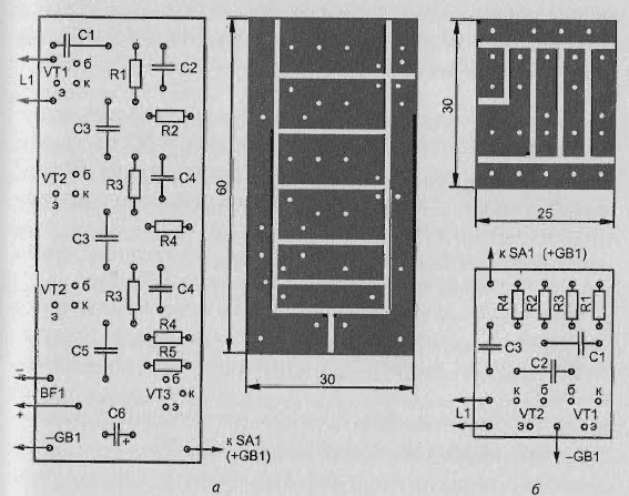
Sketches printed circuit boards and the arrangement of parts shown in Fig. 2.14, a-b.

Fig. 2.14. Sketches printed circuit boards and all details
All metal elements located inside the coils of the receiver and transmitter (battery, motherboard parts, power switch), affect their magnetic field. To exclude a possible change in their status in the process operation they must be securely fastened. This is especially true battery "Krona" as a replaceable subassembly.
Establishing
To test the operation of the transmitter instead of the coil L1 need to connect the phones and make sure that when the power is turned on in the phones the sound. Then, by connecting the coil to control the current consumed transmitter. It needs to be in the range of 5-7 mA.
The receiver is set up with closed-circuit input. The selection of resistor R1 in the first stage and R3 in the second you should install the manifolds, respectively transistors VT1 and VT2 voltage approximately equal to half the supply voltage. Then the selection of the resistor R5 is necessary to ensure that the collector current transistor VT3 became equal to 5-7 mA.
After that, Razumkov input, connect it to the receiver coil L1 and, taking the signal from the transmitter at a distance of about 1 m, to verify that the system as a whole.
Author: V. Solonenko


