In carrying out various works - earthworks, road and building construction it is often necessary to find under a layer of earth, snow, ice cover firefighters and cable wells or hidden in the walls of various metal products.
The device, described below, is used to determine the location such items in the thickness of non-magnetic mass, with little conductivity. For example, under a layer of soil, asphalt, snow can be found the cast iron cover water manhole to a depth of 0.6-0.8 m, to detect under wooden or concrete floors, and in walls, ceilings location metal beams, pipes or electric cables with metallic armour on a distance of 0.2-0.4 m (depending on the size and shape of the latter). Can also to know the direction of beam propagation reinforcement in concrete structures up to the depth of 0.1-0.15 m, etc.
This device is small in size, simple in pattern and designs; its manufacture under the force of ham secondary qualifications.
The operation principle is based on the change of natural frequencies of vibrating circuit when approaching his coils a metal object. If the circuit included in the circuit of valve oscillator, a change in inductance will change the oscillator frequency, and this change can be relatively simply to register. The magnetic field arising from eddy currents induced in finds the object, interacts with the inductance of the oscillating circuit, reduce it and thus increases the frequency of natural oscillations of the circuit. The maximum frequency change indicates a minimum distance of the frame to the metal body.
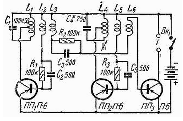
Schematic diagram of the device, which consists of two LC-oscillators and mixer, collected on the crystal triode shown in Fig. 1.

Fig. 1
The first oscillator has a tuned circuit L1C1. Coil L1 is made in the form framework, which finds the location of a metal object.
The second oscillator circuit L4C4 support, it serves as reference frequency for determining the change in frequency of the first generator.
The AC power from both generators with windings L3 and L6 is supplied to the base of a mixing triode FG3. In its collector circuit currents arise with the frequency of the first and second generators, as well as the difference and sum currents frequencies and their harmonics.
Low-frequency components of these currents are tapped on phones, included in the collector circuit of the triode FG3.
Previously the frequency of the second generator is aligned with the first frequency that is controlled using the phones for the hearing on "zero-beat". When the approximation of the frame unit to a metal object, the frequency of the first generator increases, and the phone starts
to listen the low frequency tone. The closer the frame is a metal object the higher the frequency of the first generator, the more difference frequency at the output mixer and pitch is heard in the phones. When you remove the frame from metal object oscillation frequency of the signal is heard in the phones, reduced. The highest tone is determined by the minimum distance from the frame to finds of the subject.
Frequency generators selected in the range of 80-120 kHz, and the frequency you are listening to upon detection of the subject, should not exceed 3-4 kHz.
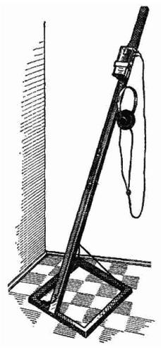
General view of the device shown in Fig. 2. All circuit elements of the device, including the power source are accommodated in a common housing, attached to the upper arm of the frame. Power is supplied from batteries for your flashlight.
The resonant circuit of the first oscillator is made in the form of separate frames, connected to a shielded instrument cable. The frame is fixed on a wooden the frame (Fig. 2) which is pivotally connected to the arm.

Fig. 2
In working condition, the frame is held in a predetermined relative to the handle position by means of a cord. When carrying frame is attached to the handle and fixed by valve.
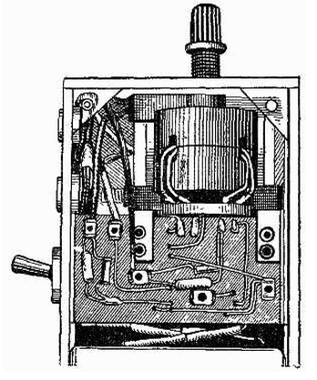
The whole installation is on a laminated bakelite Board, breaker BK1 and phone nests are fixed on the housing - Fig. 3.

Fig. 3
Setting knob (setting the core of the coil LA) is output to the outside through the hole in the side wall of the housing.
Template for winding coil frame is in the form of a rectangle of dimensions 300x400 mm of boards or sheet of plywood. In the corners of this rectangle hammered nails, they are wound with windings L1, L2 and L3.
To bond the turns of the coil must be tie a strong thread, then the frame can be removed from the nails.
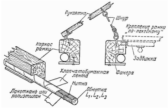
To protect the winding frame from moisture, it should be wrapped with a tape made of varnished cloth or thin polyethylene. The outside frame is wrapped in cotton tape impregnated with bitumen varnish (Frame varnished 6-8 times. After each coating of lacquer to dry well.).
The capacitor C1 and the end of the interconnect cable also insulate from moisture, and special attention should be paid to sealing the cable.
After impregnation, the frame is attached to the frame using strips of plywood as it is shown in Fig. 4.

Fig. 4
Connection cable made from three flexible wires in vinyl chloride insulation inmates in the General screen, which is worn outside or vinyl chloride rubber tube. The screen at the same time serves as a common wire for the windings L1, L2, L3 and is connected to the negative clamp of the device.
Inductors L4, L5 and L6 are wound on core SB-4. Their data the windings are shown in the table.
Designation scheme The number of turns Wire L1 15+40 PELSHO 0,6 L2 10 PELSHO 0,25 L3 2 PELSHO 0,25 L4 60+200 PEL of 0.2 L5 40 PEL of 0.2 L6 2 PEL of 0.2As the semiconductor triodes FG1, FG2 and FG3 can be used any triode type P-6, P-13, P-14, P-15 or similar.
Instrument setup is to set the capacitance of the capacitor C4 or number of turns of the inductance L4, so that in the middle position of the trimpot core frequency of the second oscillator is equal to the oscillation frequency of the first generator.
The alignment of the frequencies produced by electronic oscilloscope and the auxiliary generator on Lissajous figures.
If the frequency of the second oscillator is below the frequency of the first oscillator, to reduce the capacitance C4 or decrease the number of turns of the coil L4, if the frequency the second generator above is the capacitance of the capacitor C4 is necessary to increase or add a few turns on the coil L4.
Final adjustment of the frequency of the second oscillator is made to the hearing on "zero-beat", or watching the low-frequency signal output from the mixer to the oscilloscope.
In case of absence of the oscilloscope and the generator and the instrument can produce using a conventional broadcast receiver having far range. It is desirable that this receiver electro-optical indicator settings.
First, the measured frequency of the first generator. This is disconnected from the circuit power emitter FG2, and the mixer output (if enabled phones or substitute their resistance 4-5 ohms) through capacity 15-20 PF is connected to socket "Antenna" receiver.
Changing the setting of the receiver, the characteristic noise in the loudspeaker or the indicator settings, on the scale of the receiver determine the frequency of one of the harmonics the first generator. Changing the setting of the receiver determines the frequency of the next the harmonics. The frequency difference between two adjacent harmonics and will be equal to your own the frequency of the first generator.
Such measurements are made and the frequency of the second oscillator (with disabled the emitter (PP1).
The selection of the capacitance of the capacitor C4 or a change in the inductance L4 the frequency of the second oscillator is selected such that its harmonics auditioned on the same scale divisions of the receiver as that of the first generator.
Final frequency adjustment is made at the hearing on "zero-beat" in phones.
The setting should be considered finished, if it is possible to achieve "zero beat" with the middle position trimming core in the inductance L4.
Operation is simple and requires no special training. Before searches should include the power to the unit and listening for his work on phones, the rotation of the screw trimming core is necessary to achieve "zero beat". Then slightly Unscrew the core, to slightly detune the second oscillator with the fact" that in phones were tapped in a low tone. The device will have the highest sensitivity, as in the fine-tuning of both oscillators they mutually synchronized and at small frequency variations (when hit in the box to the frame small or faraway objects), the second generator as if "interested" the first, and the object cannot be found.
With a slight detuning even a small deviation of frequency of the first generator when approaching a metal object causes a change in height tone, which is easily detected by ear.
The search is performed by carrying the frame at a short distance from the surface ground, floor, ceiling etc. in the area of the proposed location metal object.
By rocking the frame from side to side on the change of tone is easily determined the exact location of the finds of the subject.
One battery flashlight is sufficient for operation of the device during 100-150 hours when powered by batteries of type D and 0.2 it can work 45-50 hours.
The device is unsuitable for finding small items: bolts, washers, nails and etc.
Author: Dmitry Ilyin


