


")

One of the features of all the detectors of type BFO, the support and exemplary generators these devices is designed on the elements of one chip.
It should be recognized that in addition to certain advantages (e.g. ease of schema temperature stabilization) these designs have several disadvantages. Main one of them is the occurrence of parasitic relationships between the individual elements inside the crystal chip fix which is almost impossible. That is why in such the detectors have to choose the frequency of the beating is more than 100-300 Hz inevitably reduce its sensitivity.
Attempt to deliver metal detectors operating on the basis of the analysis signal of the beating, at least from these shortcomings have been taken when creating the device, which was based on the scheme published in the domestic and foreign periodicals in the mid 90-ies of the last century.
Schematic diagram
The proposed design represents one of many options of detectors type BFO (Beat Frequency Oscillator), that is, device, based on the principle analysis of the beating of the two signals, close in frequency. In this structure, the change in frequency the beating is done by ear.
The basis of the scheme of this device (Fig. 3.6) consists of the measuring and reference generators, mixer, low pass filter, analyzer and schema acoustic indication.
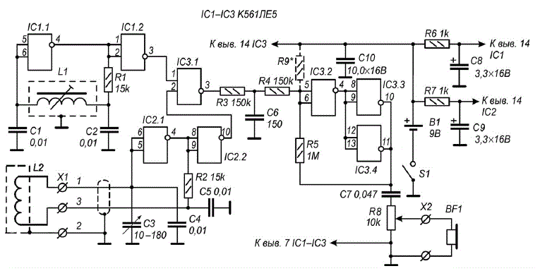
Fig. 3.6. Schematic diagram of the detector with high sensitivity
Measuring and reference generators are two simple LC oscillator, performed on the elements of the chips IC1 and IC2. In this reference generator is assembled on the element IC1.1, and measuring or tunable oscillator - on element IC2.1.
The oscillation frequency of the reference oscillator is determined by the parameters of its elements contour, i.e., the inductance of the coil L1 and the capacitors C1, C2. The values of these parameters are chosen so that the operating frequency reference frequency was about 100 kHz. Resonant circuit measuring the oscillator consists of the search coil L2 and capacitors C3-C5. Working the frequency of this oscillator is close to the frequency of the reference oscillator and can be slightly modified by adjustment of the variable capacitor C3. Elements IC1.2 and IC2.2 perform the function of cascades, providing isolation between generators DC voltage.
From the outputs of the two generators, the RF signals are fed to the mixer made the element IC3.1, the output of which oscillations are generated with the total and difference frequency generators and their harmonics, arriving at the circuit low pass filter.
Unlike many other detectors type BFO in the proposed device for the selection differential signals (audible) frequencies of the applied low pass filter which is assembled on the elements R3 and C6. Further, the signal LF is supplied to the analyzer.
As is known, the sensitivity of the detectors metal objects, evaluating the frequency of the beat signal largely depends on the signal which the lowest frequency can be registered with this unit. Best sensitivity have metal detectors, providing the analysis of heartbeat a frequency of several Hertz. However, to listen to the signal directly to headphones impossible due to the limited operating range of frequencies telephone earpieces.
Quite often developers have resorted to the simplest solution to this problem, namely: just increase the frequency of the beat signal by using different multipliers. One option doubler frequency (more precisely, the transformation a sinusoidal signal into a sequence of pulses of twice the frequency) already been reviewed in the previous Chapter when describing the transistor with the metal detector heightened sensitivity.
In the analyzer of the detector for the considered increasing the frequency of the signal beating scheme is applied, which convert the sinusoidal (almost triangular) signal in short pulses at twice the frequency. For this uses a voltage comparator, performed on the elements of IC3.2-IC3.4. For one period of the beat frequency twice comparator switches from one logical state to another, then it generates rectangular pulses differentiate circuit C7R8 and then through capacitor C7 serves on the regulator the volume of the R8. As a result, the headphones BF1 connector x2, do short voltage pulses of twice the frequency.
The device is powered from the source B1 voltage of 9 V. the chips IC1 and IC2 of the detector is fed from a DC source through decoupling filters R6C8 and R7C9.
Details and design
All the details of the considered detector (with the exception of the search coil L2, resistor R8, capacitor C3, connectors X1 and x2, as well as switch S1) located on the PCB size 80x60 mm, made of two-sided foil Micarta or phenolic resin (Fig. 3.7). Mounting elements runs from the conductors, and foil on the other hand plays the role of screen.
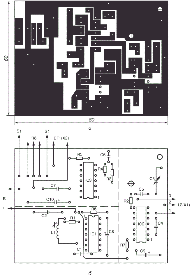
Fig. 3.7. Printed circuit Board (a) and the arrangement of elements (b) of the metal detector with high sensitivity
To detail used in this device without facing any special requirements. It is recommended to use any small-sized capacitors and resistors that can be placed on the circuit Board.
Capacitor C3 should have a maximum capacity of 180 to 240 pF. You can use any capacitor from small-sized radio (for example type KP-180). To improve the thermal stability it is desirable that the capacitors C1, C2, C4 and C5 had not TKE worse M1500. Fixed resistors may be, for example, type MLT-0,125.
Chip type CLE you can replace chips CLE, or CLA CLA.
Coil L1 consists of 30 turns of wire sew-2 with a diameter of 0.08 mm. For its winding it is recommended to use a frame from the coil circuit of the inverter transistor radio (for example, "the Mountaineer-407 or equivalent).
The search coil L2 has 100 turns of wire sew-2 with a diameter of 0.6 mm and made in the form of a torus with an inner diameter of 240-250 mm. This reel for easier to manufacture on a rigid frame, but you can do without it. In this case as a temporary frame may be any suitable size round object, for example the Bank. The turns of the coil are wound in bulk, and then removed from frame and screened electrostatic screen, which has to be made on top of the bundle of turns of the wound tape from aluminum foil. The gap between the beginning of and the end of winding of the tape (the gap between the ends of the screen) should be about 10 mm.
In the manufacture of the coil L2, it is necessary to ensure that did not happen the closure ends of the shielding tape, as in this case, a closed loop is formed. To increase the mechanical strength of the coil before shielding can be impregnated with epoxy glue. To the terminals of the coil should be soldered conductors double-shielded cable length of about one meter, at the other end of which fits the socket type SS-3 or any other suitable small-sized connector. The braided cable should be connected to the screen coil. In the working position coil connector connects to a return connector part located on the housing of the device.
Food metal detector with high sensitivity is provided from source B1 voltage of 9 V. as such a source can be used for example, the battery "Krona" or two batteries type 3336L, United consistently.
Printed circuit Board with the controls it contains and the power source are placed in any suitable metal enclosure. On the housing cover installed capacitor C3, variable resistor R8, connector X1 for connection search coil L2, the switch S1 and the connector x2 for connecting headphones BF1.
Establishing
Consider the detector should be set in the environment when metal objects removed from the search coil L2 at a distance of not less than 1.5 m Direct configuration of the device should begin with the selection of the desired frequency of the beats. It is recommended to use the oscilloscope or digital the frequency counter.
When working with the oscilloscope probe must be connected to the input of a low pass filter (pin IC3/3). The waveform at this point is reminiscent of the waveform the modulated RF signal. Further, adjusting coil L1, and optionally selecting the capacitance of the capacitors C1 and C2, it is necessary to ensure that the frequency modulation (beat frequency) would be equal to approximately 5-10 Hz.
When using a digital frequency meter to adjust the metal detector frequency should be connected to pin 1 of IC3, and then connects to pin 2 of this same chips. By changing the parameters of the previously listed elements (inductance coil L1, the capacitance of the capacitors C1 and C2), it is necessary to ensure that the frequency difference between the signals at these points also equaled approximately 5-10 Hz.
To select the desired beat frequency and oscilloscope and frequency counter. In this the case is usually sufficient to adjust the operating frequency of the reference oscillator. For this purpose to the output of the element IC3.1 (pin IC3/3) you need to connect a high resistance phones (such as the TONE-2), and then by adjusting the trimpot core of the coil L1, to achieve the appearance in the head phones the audio signal. The rotor capacitor C3 should be set to the middle position. Then, by rotating trimming the core of the coil L1, it is necessary to set the mode in which the the phones will use to listen for clicks, following with a frequency of several Hertz. After adjusting the oscillator trimmer core of the coil L1 preferably locks with the drops of glue.
Next, you need to configure the comparator voltage. You need to choose the the resistor R9 as shown in Fig. 3.6 dashed lines. It the resistance can be in the range of from 300 ohms to 1 MOhm. It should be noted, the resistor R9 should be inserted between pin 5, 6 of the element IC3.2 General wire when the output of the comparator (pins IC3/10,11) voltage high level.
The order of work
In the practical use of this device is a variable capacitor C3 to maintain the desired signal frequency of the beats, which can change under the influence of various factors (for example when changing the magnetic properties of the soil, the ambient temperature or battery discharge).
If in the process of work in the area of the search coil L2 will be any metal object, the frequency of clicks in headphones change. When approaching one of the metals it will increase, and when approaching others - to decrease. To change the frequency of clicks with a certain experience, it's easy to determine the kind of metal, magnetic or non-magnetic, made the detected object.
Click volume is regulated by a variable resistor R8.
Author: M. V. Adamenko