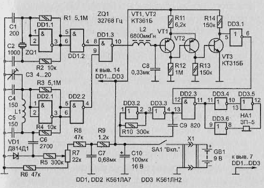
Schematic diagram of the detector is shown in Fig. 2.12. Reference oscillator 32768 Hz assembled on the logic element DD1.1 and the quartz resonator ZQ1.
Search generator made on the element DD2.1 and the coil L1, representing a gauge of the metal. In addition, the generator consists of a chain of frequency - trimmer capacitor C3 and the node e of frequency tuning in the Zener diode VD1, playing the role of the varicap.
The elements DD1.2 and DD2.2 - a buffer. The element DD1.3 performs the function of the adder, his load is a filter L2C8, which suppresses high frequency oscillations, but ignores the low beat frequency.
Transistors VT1, VT2 assembled a Schmitt trigger, which from the signal that is close in the form is sinusoidal, generates rectangular pulses. Amplifier the transistor VT3 increases the amplitude of the pulses to a level equal to the supply voltage. Element DD3.1 completes the formation of rectangular pulses and inverts them.

Fig. 2.12. Schematic diagram
These pulses are received at one input element of coincidence DD2.3, and to the other input summed rectangular pulses with a frequency of 2 kHz with the output of the generator inverters DD3.2, DD3.3. Elements DD3.4-DD3.6 play the role of the output amplifier for a piezoceramic sound projector HA1.
Eats the metal detector from the battery GB1.
Setting of the metal detector
Before starting to search for hidden metal objects is to achieve zero beat on the output of the adder DD1.3 or, in other words, set exact equality of the values of the generator frequency.
For this purpose, the sensor device is a coil L1 to need:
- be placed in a location remote from the earth and metal objects at a distance not less than 1 m;
- to turn on the device;
- variable resistor R7 to transfer to the middle position;
- rigged capacitor NW to set such a frequency search generator, wherein Zvyozdy - Catal HA1 reproduces rare short tones or even be silent;
- to achieve a rotation in very small within the handle of the variable resistor R7 the complete cessation of sound.
Now the sensor should be lowered to the ground and slowly start to drive over it surface, listening to the sound of the instrument. With the approach of the sensor to a metal the subject appear rare short tone signals that gradually become more frequent and, finally, merge into an almost continuous roar.
Working principle diagram
At zero beat difference frequency generators are zero, the input trigger Schmidt of voltage fluctuations not, so it doesn't switch. Transistor VT3 is closed, the output of the inverter DD3.1 low level, so the element DD2.3 not skips to the output amplifier of the oscillation generator DD3.2, DD3.3.
Once the coil L1 is closer to a metal object will change its the inductance, and hence the frequency of the search oscillator. At the output of the filter L2C8 appears alternating voltage. The bigger the object the closer the sensor, the higher the beat frequency.
This leads to more frequent opening of the element DD2.3 and increase the frequency repeating audible tone. The frequency of the generator on the elements DD3.2. and DD3.3 (2 kHz) is selected close to the natural frequency of the piezo oscillator SN-5 for the purpose maximum volume of the signal.
Components and replacement
The detector uses a quartz resonator hour type, but the fit and other resonators at the frequency of 80-100 kHz. However, you will have to adjust the number of turns of L1 and the values of capacitors in the generators. Capacitors C1, C2, C4, C5 should be chosen with minimum TKE. AC the resistor R7 must be the group A.
Transistors CTB can be replaced by CTC. CTL and KT315B - CTHM, KT3102EM. Instead RFP-5 can be used and other pietistically. Power source - battery "Corundum" or the battery.
The design of the metal detector
Cost with the items it is advisable to place in a small, durable plastic box, to which will be attached to the coil-sensor L1. The coil should contain 450 turns of PEV-2 0,18. It must be wound on a round boss with a diameter of 210 mm, then remove and wrap with adhesive PVC tape. Coil resistance is about 200 Ohms.
The coil should be placed in a rigid screen that represent open-loop the ring and bent from mild dural tube. Along the tube needs to saw a groove with a width sufficient to lay inside of the coil insulated with tape. Screen with stacked coil to tightly wrap adhesive PVC tape and two screws to attach to the box with the card.
Unused pins of the ICS DD1, DD2 should be connected positive to the positive wire power.
Installation of zero beat
Sometimes fails to set the zero run-out. The reasons may be such:
- low battery power;
- malfunction of the variable resistor R7;
- frequency instability of oscillators.
Power to each of circuits is advisable to apply through a RC-filter. The filter capacitor has a capacitance of 0.01 μf should be soldered directly to pins, and a resistor is better to pick up experimentally.
Author: L. Kononenko


