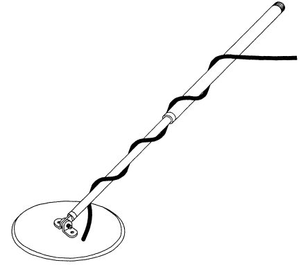
The disk sensor is a traditional metal detectors on the beat, for metal detectors on the principle of "transmit-receive" with coplanar arrangement coils, also it is suitable for induction, pulse metal detector, and for the metal detector on the principle of electronic frequency counter. The sensor is attached to the rod (see Fig. 35).

Fig. 35. The appearance of the disk of the sensor on the rod
Rod can be made of metal or fiberglass. Convenient telescopic sliding rod. In Amateur purposes, you can use 2-3 of the knee from telescopic fiberglass fishing rods suitable thickness. Non-metallic rod is preferable in view of the absence of large masses of metal near sensor.
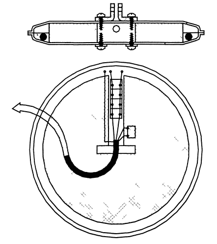
The sensor has the shape of a hollow disc made of plastic. Coil, fasteners and other items are placed inside. Below are considered practical the design of this probe with a single coil, proposed by the author (Fig. 36).

Figure 36 Structure of the disk sensor
The sensor consists of upper and lower covers 1 and 2, which are used as plastic lid from a set of plastic utensils. Cover connected another by welding. Welding plastic lids carried on the shoulder, available on the edge of each cover, using a soldering iron with a special nozzle. The nozzle on the tip of a soldering iron for this kind of welding is a "V"-shaped in the cross section of the tray. The inner surface of the nozzle-heated tray the contiguous edges of the lids to melt in one place, and then gradually moving the soldering iron with a nozzle at the tray, bypass the entire circumference contact the edges of the lids.
Before performing such welding completely, it is recommended to practice on the test samples. You will need to select the desired temperature of the nozzle-tray (power soldering iron 40 W), the speed of movement of the tray during welding. Recommended soldering iron with a nozzle at the tray still to fix, for example in the Vice and welded parts to hold in your hands. To molten polyethylene is not accumulated in the nozzle-tray and for more neat seam the movement of the nozzle-pan around the circumference must be combined with its rocking translational oscillation amplitude of 2...5 mm. Described the operation of welding plastic parts are time-consuming, but the resulting sealed, lightweight and durable the sensor housing is worth the cost.
In addition to welding, the additional fixing of the covers 1 and 2 by means Central bars made of vinyl plastic. It is attached to the bottom cover with screws-screws. After Assembly of the sensor to a Central plank also screwed the corners of the suspension of the sensor.
The main "highlight" of the sensor is unusual for any other designs the combination of foam and epoxy. Foam made disc filler 3 sensor. The foam can be used almost any. Widely available packaging and insulating foam (friable, easily crumbled by hand on individual beads) is even more preferable than solid as it has more than large and even through pores that are filled later with epoxy. Disc 3 occupies most of the volume sensor and the light weight gives it the necessary stiffness. The disc is cut out using a hot metal filament (spiral the electric heating device) connected to the low voltage power source. If you have a foam sheet of the required thickness, it is necessary tools need is a jig saw or a razor blade. In disc 3 cut the slots required shape and size for the Central strap, cable 8, a capacitor 6 and to other elements 7 of the electrical circuit of the sensor.
The coil 4 is placed on the outer edge of the disk 3 and filled with epoxy resin 5. Winding wire is wound the required grade and gauge mandrel diameter, greater than the diameter of the disk 3 by approximately 5 mm. Carefully removed from the mandrel the winding is secured in four places with adhesive tape to give it shape thin ring. Then this ring is wrapped with adhesive tape (better to use paper) - width 5 - 10 mm, with the maximum tension (figure 37). Winding sticky the tape needs to happen so that adjacent turns of tape had sufficient overlap. This overlap gives the winding of the sensor is desired stiffness.

Figure 37 Winding reel tape
In a similar way over the top layer of tape is applied a layer of aluminum foil serving as a screen winding of the sensor. For this purpose, the foil is cut into stripes width of about 10 mm To prevent formation of a closed loop, reducing the factor of the circuit, the coil of foil should not take all ring surface of the winding of the sensor is from the foil is left free small section length of 1 to 2 cm So that the foil does not rewound itself past the coils fixed with adhesive tape. The drain from the screen is solid tinned wire without insulation. The wire is fixed by the node or by using adhesive tape in the beginning of the winding of the foil screen and then also with the tension wound on top of the screen to its other end. The remaining end of the wire fix with adhesive tape and leave for connecting a free end length of 5... 10 cm At the end the ring is wrapped with a winding of the sensor on top of duct tape over the entire surface, releasing output terminals of the winding and the screen.
The described method of fabricating a shielded coils sensors metal detectors are available for duplication in Amateur conditions. It does not require such time-consuming procedures, such as impregnation (epoxy, paraffin and etc.), and the mechanical rigidity of the winding becomes high, especially when pouring epoxy on the outside.
The Assembly of the sensor occurs in the following sequence. The bottom cover 2 sensor with the inside set of the Central bar, set the foam disk 3 and the coil 4, through openings in the upper cover 1 and Central plank pass through the cable 8 and cut up his end. Then set the remaining elements of the electrical circuit of the sensor capacitors, resistors, etc. - and produce them with soldering pins of the cable and coil winding sensor. The thermistor compensation induction metal detector with it is advisable to install in the immediate vicinity of the coil. For convenience the radioactive elements can be mounted on a small PCB layout.
After that, the sensor is mounted on a horizontal surface and foam disc 3 press cargo that does not pop up in epoxy resin. Then produce the fill sensor with resin or epoxy and hardener. The ability of the resin or glue to cure, you must check in advance in order not to damage the sensor! Pour the sensor it is recommended to the edges of the bottom cover 2. Not recommended to work with epoxy resin at temperatures below +15 °C, as a cure may take several days, and above +25 °C due to turbulent flow the curing reaction with the release of large amounts of heat which can to deform the sensor.
After solidification of the resin cable 8 is placed in the cut out under it in disc 3 groove, sealed his exit in the hole of the upper cover 1 silicone sealant and set the top cover in place, secure it with self-drilling screws on Central plank along with the suspension parts. In conclusion, produces a weld the upper and lower lids of the sensor housing using the method described earlier.
Author: A. I. Shchedrin


