The proposed detector is designed for "middle". It assembled on a simple scheme. The device is compact and simple to manufacture. Depth detection is:
- coin
 25mm - 5 cm;
 - gun - 10 cm;
- helmet - 20 cm
Structural scheme
Structural diagram depicted in Fig. 8. It consists of several functional blocks. A crystal oscillator is a source of rectangular pulses of stable frequency.
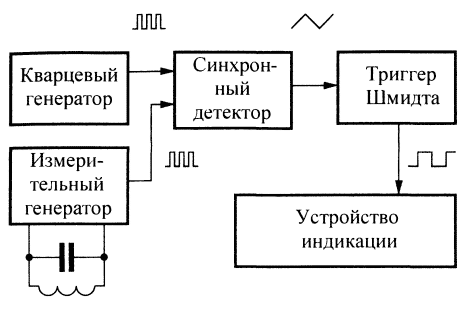
Fig. 8. Block diagram of the detector on the beat
The measuring generator connected to the resonant circuit, which includes the sensor coil inductance. The output signals of both generators arrive at the inputs of the synchronous detector, which at its output generates a difference frequency signal. This signal has approximately sawtooth shape. For the convenience of further processing of the signal synchronous detector is converted by using the Schmidt trigger in signal rectangular form. Display device is designed to form sound signal of the difference frequency by using the piezo oscillator and for visual show the magnitude of this frequency with led indicator.
Schematic diagram
Schematic diagram developed by the author of the detector on the beat depicted in Fig. 9.
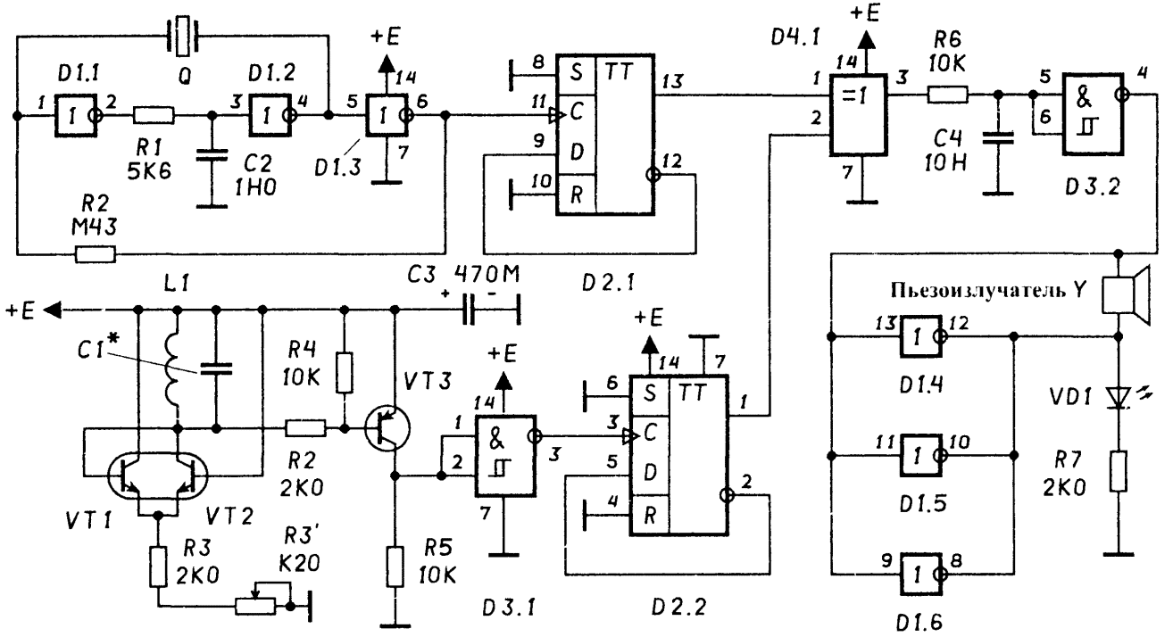
Fig. 9. A circuit diagram of metal detector on the beat (hit to enlarge)
A crystal oscillator has a scheme similar to the scheme of the generator of the detector on the principle of "transmit - receive", but implemented in the inverters D1.1-D1.3. Frequency generator stable or crystal / ceramic resonator with Q the resonance frequency of 215 Hz ~ 32 kHz ("quartz clock"). Chain R1C2 prevents the excitation of the generator at higher harmonics. Through the resistor R2 this completes the circuit The PIC through the resonator Q - chain PIC.
The generator is simple, low power supply current from the power source, reliably operates with supply voltage of 3..15, does not contain a setup elements and too high resistance resistors. The output frequency of the generator is about 32 kHz. Additional counting trigger D2.1 required for the formation of the signal with a duty cycle is exactly equal to 2, for later schemes synchronous detector.
The measuring generator
Directly generator is implemented on the differential stage transistors VT1, VT2. Chain PIC is implemented electrically, which simplifies the circuit. Load differential stage is oscillating circuit L1C1. Frequency generation depends on the resonant frequency of the resonant circuit and, to some extent, from sensitive current differential stage. This current is set by resistors R3 and R3'. The tuning frequency of the measuring oscillator with the setting of the device is roughly the selection of the capacitance C1 and sliding adjustment potentiometer R3'.
To convert low voltage output differential stage to standard logic levels of digital CMOS circuits is the cascade scheme with common emitter transistor VT3. Driver with Schmitt trigger input on element D3.1 provides a steep wavefronts for normal operation subsequent counting of the trigger.
Additional counting trigger D2.2 necessary for the formation of the signal with the duty cycle is exactly equal to 2, for later schemes synchronous detector.
Synchronous detector
The detector consists of a multiplier that is implemented on the element D4.1 "Exclusive OR" and the integrating circuit R6C4. Its output signal is similar in form to sawtooth, and the frequency of this signal is equal to the difference frequency of the quartz generator generator and measuring.
The Schmitt Trigger
The Schmitt trigger is implemented on the element D3.2 and generates rectangular pulses of the sawtooth voltage of the synchronous detector.
A display device
Is just powerful inverter buffer implemented on the three remaining the inverters D1.4-D1.6, switched in parallel to increase the load ability. Load indicating devices are the led and the piezo oscillator.
Types of parts and design
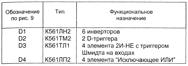
The types of chips are shown in table. 4.
Table 4. The types of chips
Instead of chips series C may use chipset series C. Can try to apply some chips series C. The unused inputs elements of digital circuits cannot be left unconnected! They should to connect with either a shared bus or from the power bus.
Transistors VT1, VT2 are integral elements of the transistor Assembly type CNT with any letter. They can be replaced by discrete transistors with n-p-n conductivity types KT315, CT etc VT3 Transistor - type KT361 with any letter or similar type with p-n-p conductivity.
To applied in the circuit of the detector resistors are not required special requirements. They should be of sturdy construction and be easy to assemble. Rated power dissipation must be 0,125 0,25...watts.
The compensation potentiometer R3' desirable multi-turn type SP5-44 or Vernier tuning type SP5-35. You can do the usual potentiometers any types. In this case, it is desirable to use two series included. One for coarse adjustment, with a value of 1 kOhm. Another for the exact adjustment of par value of 100 Ohms.
The inductor L1 has an inner winding diameter 160 mm, contains 100 turns of wire. Wire - PEL, sew, PELSHO, etc. wire Diameter 0,2...0,5 mm On the coil design, see below.
Capacitor Sz - electrolytic. Recommended types - C50-29, K50-35, K53-1, K53-4 and other small. The remaining capacitors, except capacitor resonant circuit coil of the measuring generator, - ceramic type K10-7, etc., Capacitor circuit C1 special. To him high demands are placed on accuracy and thermal stability. Capacitor consists of several (5...10 pieces) individual capacitors included parallel. Coarse tuning circuit to the frequency of the crystal oscillator occurs by adjusting the number of capacitors and their value. Recommended the type of capacitors K10-43. Their group on the thermal stability of refraction (i.e. approximately zero TKE). Perhaps the use of precision capacitors and other types, such as K71-7. In the end, you can try to use thermostable mica capacitors with silver plates type CSR or polystyrene capacitors.
VD1 led type AL or equivalent with high efficiency. The fit and any other led visible light.
Quartz resonator Q is any compact quartz clock (similar are also used in portable electronic games).
The piezo oscillator Y1 - can be type LU1-SP. Good results are obtained when the use of pied - posluzitelja import of phones are coming in huge amounts "to the dump" in the manufacture of phones with caller ID).
The device design can be arbitrary. It it is desirable to consider the recommendations set out in the sections on sensors and hull designs.
PCB electronic part of the detector can be manufactured by any of traditional methods, it is convenient to use a ready breadboard PCB under the DIP IC packages (pitch 2.5 mm).
The establishment of the device
The establishment of the instrument is recommended in the following sequence.
1. To verify the correctness of installation of the power scheme. To ensure the absence of short circuits between adjacent conductors of the circuit Board, adjacent legs of the chips, etc.
2. Connect the battery or power source 9, in correct polarity. Turn the unit on and measure current consumption. It needs to be about 10 mA. A sharp deviation from the specified value indicates wrongness installation or faulty circuits.
3. To verify the output of the crystal oscillator and the output element D3.1 clean square wave with a frequency of about 32 kHz.
4. To verify the outputs of the triggers D2.1 and D2.2 signals with frequencies about 16 kHz.
5. To verify the presence of the input element D3.2 sawtooth the difference frequency, and its output is a rectangular pulse.
6. Make sure that the display device is visually and aurally.
Possible modifications
Diagram of the device is extremely simple and therefore it can only go on further improvements. These include:
1. Adding additional logarithmic led display frequency.
2. The use of transformer sensor in the measuring generator.
Consider these modifications in more detail.
Logarithmic frequency indicator
Logarithmic frequency indicator is an improvement the led indicator. The scale consists of eight individual LEDs. When the measured frequency of a certain threshold, on the scale lights up the corresponding led, and the remaining seven do not burn. Feature indicator is that the threshold frequency for the neighboring LEDs differ from each other twice. In other words, the scale of the indicator has logarithmic graduations, which is very convenient for such a device, as the metal detector on the beat. Schematic diagram of the logarithmic indicator the frequency is shown in Fig. 10.
Despite the fact that the scheme of this indicator was developed by the author independently, it does not claim to originality, as performed a patent search has shown that such schemes are known. Nevertheless, as herself scheme of the indicator and its implementation on the domestic element base is, in the author's opinion, of particular interest.
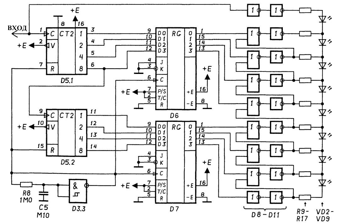
Fig.10. A circuit diagram of the logarithmic indicator (press to enlarge)
Works logarithmic indicator as follows. To the input of the indicator receives the signal from the output of the Schmidt trigger circuits of the detector on the beats (see Fig. 9). This signal is an input to binary counter D5.1-D5.2 (the numbering continues the numbering scheme Fig. 9). These counters periodically reset by the signal of high level auxiliary generator the Schmitt trigger D3.3 with a frequency of about 10 Hz. On the leading edge of the signal the auxiliary generator is also writing the state of the counters in parallel four-digit registers D6 and D7. Thus, the outputs registers D6 and D7 there is a digital code signal frequency of the beats. To convert this code into a logarithmic scale may simply (and in this "highlight" of this scheme), if the ignition of the corresponding diode scale to match the appearance of the units in a particular category code frequency when all zeroes in the older bits of code.
Obviously, this task needs to perform combinational circuit. The simplest the implementation of such a scheme is a periodically repeating unit of elements OR. In practical circuit elements OR-NOT, D8, D9 together with powerful buffer inverters D10, D11. The circuit output is obtained logic signal controlling the LEDs of the scale in the form of "waves of units". From the point for saving battery power, of course, more appropriate to make the scale not in the form of a luminous column of LEDs (8 PCs.) and in the form moving from one point of glowing led. The LEDs indicator line connected between the outputs of the combinational circuit.
For very low frequencies is still more suitable indication in the form of the flashing led. In the proposed scheme it is combined with early led scale and off lights her next segment. The choice of elements R8, C5 you can change the frequency of the auxiliary generator by modifying such the scale range in frequency.
Types of parts and design
The types of chips are shown in table. 4.
Table 4. The types of chips
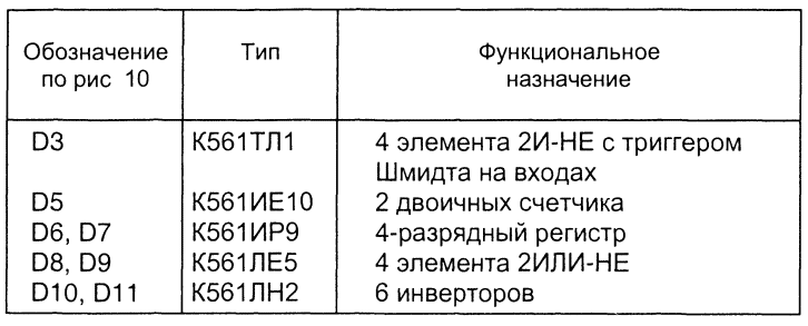
Instead of chips series C may use chipset series C. Can try to apply some chips series C. The wiring circuits and power pin numbering for chips D8-D11 for simplicity is not shown.
LEDs VD2-VD9 type AJ1336 or equivalent with high efficiency. Their dakotadome resistors R9-R17 have the same value of 1.0...5,1 kOhm. The less the resistance of these resistors, the brighter will glow the LEDs. However this may not be enough load capacity chips K561LN2.
In this case it is recommended to use parallel connected output the inverters in the circuit of the indicator. It is most convenient to arrange it parallel incorporation by simple soldering additional buildings of the same type chips (4 PCs.) over each of the installed circuit chip K561LN2.
Transformer sensor
The idea transformer sensor for metal detectors is simple and graceful. It known for a long time and has arisen because of the desire to simplify the design of the sensor coil the metal detector. The usual drawback of a typical sensor of the detector of any design is a large (over 100) the number of turns of the coil. Because of this turns out insufficient rigidity of the sensor, which requires that special measures such as additional frames, epoxy potting, etc. In addition, parasitic capacitance of a coil is great and to eliminate false signals due to capacitive coupling of the coil (coils) with the earth and the body of the operator definitely shielding windings.
The way to resolve these drawbacks in a simple and obvious - it is necessary use a coil, consisting of a minimum number of turns - one revolution! Naturally, "in a forehead" this decision is negligible the inductance of a single turn would have required giant largest vessels capacitors, resonant circuits, signal generators, big exit current and special tweaks to ensure a high quality factor. And here the most a time to remember the existence of the device designed to harmonize impedances, to convert variables from a large voltage with a small current from the low voltage with high current, and Vice versa on the transformer.
In fact, take a transformer with a transformation ratio of about one hundred and connect the lower winding of one coil, which is the sensor of the detector and increases the winding - diagram of the detector coil instead the inductance. Structurally, one coil of such transformer sensor can to be performed in a variety of ways. For example, it can be a the ring is made of solid copper or aluminum wire cross-section 6... 10 mm2 for copper and 10...35 mm2 for aluminium. Convenient to use inner cores the power cables. It is possible to reduce weight and increase stiffness to produce round metal tube. It is possible to manufacture a coil of aluminum foil by stickers on the sheet material, and even regular foil fiberglass. In any convenient place coil is grounded by connecting to a common bus of the device, which ensures compensation of the parasitic capacitive links. The impact of these relations in this structure, the sensor is several orders of magnitude less due to the smaller values of the modulus of the impedance of a single turn.
Transformer sensor allows you to implement a collapsible compact design the metal detector on the beat. The sketch is depicted in Fig. 11. Transformer sensor performed on the toroidal magnetophone installed directly on the Board the detector, placed in a plastic housing. Down winding transformer and coil sensor constructively represent a single entity in the form of a rectangular frame composed of copper insulated single-conductor wire cross-section 6 mm2, closed by soldering. The specified frame has the ability to rotate.
In the folded position, the frame is located on the perimeter of the enclosure and not occupy unnecessary space. In the working position it is rotated 180°. For that frame was fixed in the prescribed position, grommets of rubber or other similar material. Possible or use any other suitable mechanical fixings for the frame.
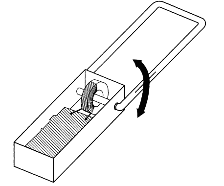
Fig. 11. The design of the detector on the beat with a folding frame sensor
Section of the conductor, made from round transformer sensor, must be not less than the total cross section of all of the turns constituting ordinary the coil of the sensor of the detector. This is necessary not only to give design the necessary strength and rigidity, but also in order not to get too low q-factor of an oscillatory circuit with this transformer the analog of the inductor (by the way, if you use this loop in a as a radiating coil, the current can reach tens of amperes!). For the same reason you need the choice of cross wire winding down transformer. He may have a smaller cross-section than the cross section of the conductor loop, but its ohmic resistance should not be greater than the ohmic resistance revolution.
To reduce losses due to the ohmic resistance must be very carefully follow the connection turns down winding of the transformer. The recommended method of connection - soldering (copper coil) and welding in the environment inert gas (for aluminum).
The transformer should meet the following requirements. First, it needs to work with low loss at the desired frequency. In practice, this means that the magnetic core must be made of a low-frequency ferrite. Secondly, it winding should not make a significant contribution to the impedance of the sensor. In practice, this means that the inductance of winding down should be more noticeable the inductance of the coil. For toroidal ferrite cores with magnetic permeability μ=2000 and a diameter of over 30 mm this is true even for one loop winding down. Thirdly, the transformation ratio should be such that the inductance increases when winding is connected to a reduction the winding coil of the sensor would be approximately the same as that of the conventional coil the model of the sensor.
Unfortunately, the advantages of transformer sensor markedly superior to his the only disadvantages to metal detectors on the beat. For more sensitive devices this sensor is not applicable because of the rather high sensitivity to mechanical deformation, which leads to false signals appearing at motion. That is why transformer sensor is seen only in section, dedicated to the detector on the beatings.
Author: A. I. Shchedrin


