Compact metal detector can detect hidden nails in the walls, screws, metal fittings at a distance of several centimeters.
The principle of operation
The detector used traditional detection method based on the two generators, the frequency of one of which changes as you move of the device to the metal object. A distinctive feature of the design - no homemade coil winding details. As inductors used the winding of the electromagnetic relay.
Schematic diagram
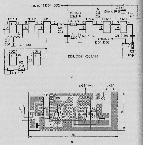
The detector (Fig. 2.19, a) contains:
- LC-generator on the element DD1.1;
- RC oscillator on the elements DD2.1 and DD2.2;
- buffer amp on DD1.2;
- mixer on DD1.3;
- voltage comparator for DD1.4, DD2.3;
- the output stage on DD2.4.
Device works well. The frequency of the RC oscillator should be set close to the frequency of the LC oscillator. In this case the PA, the mixer output will be present from not only with the frequencies of both oscillators, but with the difference frequency.
Filter low frequency R3C3 allocates the signals of the difference frequency, which is input to the comparator. On the outlet is formed rectangular pulses of the same frequency. From the output of the element DD2.4 they come in via the capacitor C5 connector XS1, the nest which is a fork of headphones with impedance of 100 Ohms.

Fig. 2.19. Small metal detector: (a) schematic diagram; b - the printed circuit Board
The condenser and phones form a differentiating circuit, so the phones you will hear clicks with each of the rise and fall of the pulses, i.e. with the doubled frequency signal. To change the frequency of clicks you can judge the appearance the equipment near metal objects.
Element base
Is indicated in the diagram is valid for use of the chip:
- CLA;
- CLA;
- CLE.
Polar capacitor - series, K52, K53, rest - room 10-17, KLS. AC resistor R1 - JS4, act, constant - MLT, S2-33. Connector with contacts which closes when inserted into the socket plug phones. Power source - battery "Krona", "Emery", "nick" or similar battery.
Preparation coil
The coil L1 can take, for example, of the electromagnetic relay RES, passport RS4.524.200 or RS4.524.201 with a coil resistance of about 500 Ohms. For this relays need to disassemble and remove the movable elements with contacts.
The magnetic system of the relay has two coils wound on separate magnetic cores and connected in series. The General conclusions of the coils must be connected to the capacitor C1, and the magnetic core also as the housing of the variable resistor, with the common wire of the detector.
The printed circuit Board
Parts of the device except the connector should be placed on a printed circuit Board (Fig. 2.19, b) of two-sided foil fiberglass. One side of it should be left metallized and connected to the common wire of the other side. On the metallized side to fix the battery and "extracted" from the relay coil.
The findings of the relay coil should pass through holes and razzenkovannoe to connect with the respective printed circuit conductors. Other details posted from the print. Fee set in case made of hard plastic or cardboard, on one of the walls which secure the connector.
Adjustment of the metal detector
Establishing device should begin with set the frequency of the LC oscillator in the range of 60-90 kHz the selection of the capacitor C1. Then you need to move the slider of the variable resistor is about average the position and selection of the capacitor C2 to achieve the appearance of sound in the phones signal. When you move the cursor of the resistor in one direction or another signal frequency must change.
For detection of metal objects variable resistor pre - you need to install may lower the frequency of the sound signal. Approaching the subject of the frequency starts to change. Depending on the settings above or below the zero beat (equality of frequencies of the generators), or the kind of metal, the frequency will change in a big or the lower side.
Author: Nechaev I.


