Schematic diagram
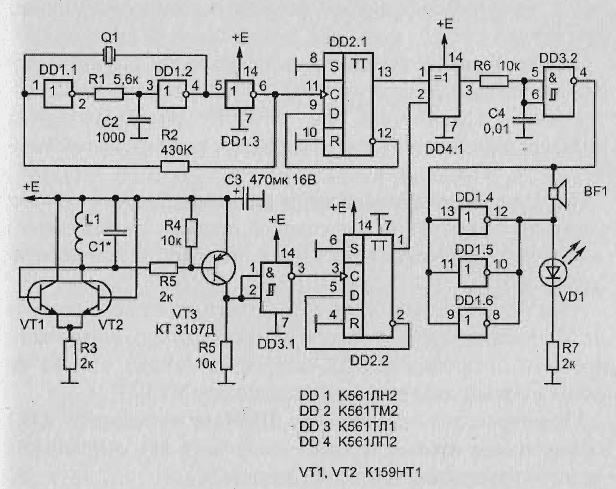
Schematic diagram of the detector on the beat is depicted in Fig. 2.49.

Fig. 2.49. Schematic diagram Kartavenko metal detector on the beatings
The scheme consists of the following components:
- crystal oscillator;
- the measuring generator;
- synchronous detector;
- the Schmitt trigger;
- a display device.
Quartz oscillator is based on the inverters D1.1-D1.3. The oscillator frequency stable or crystal / ceramic resonator with resonance frequency 32768 kHz (quartz clock). Chain R1C2 prevents the excitation of the generator at higher harmonics. Through the resistor R2 is shorted circuit environment, through the resonator Q1 - circuit PIC.
The generator is simple, low power supply current from the power source, works reliably at a voltage of 3-15 In, contains trimpot elements and too high resistance resistors. Additional counting trigger D2.1 required for the formation of the signal with the duty cycle is exactly equal to 2, for later schemes synchronous detector.
Measuring oscillator is based on differential stage transistors VT1, VT2. Chain PIC is implemented electrically, which simplifies the circuit. Load differential stage is oscillating circuit L1C1. The oscillation frequency depends on the resonant frequency of the resonant circuit and, in some extent, from sensitive current differential stage. This current is set by resistor R3.
To convert low voltage output differential stage to standard logic levels of digital CMOS circuits is the cascade scheme with common emitter transistor VT3. Driver with Schmitt trigger element D3.1 provides a steep fronts pulses for subsequent normal operation of the counting trigger.
Additional counting trigger D2.2 necessary for the formation of the signal with the duty cycle is exactly equal to 2, for later schemes synchronous detector. Synchronous detector consists of a multiplier that is implemented on the element D4.1 "Exclusive OR" and integrating chain R6C4. Its output signal is close in form to sawtooth, and the frequency of this signal is equal to the difference frequency of the quartz generator and search generator. The Schmitt trigger is implemented on the element D3.2 and generates rectangular pulses of the sawtooth voltage of the synchronous detector.
A display is just a powerful buffer inverter implemented at the three remaining inverters D1.4-D1.6, switched in parallel to increase the load capacity. Load indicating devices are led and system.
Manufacturer of coil
Coil L1 is wound on a mandrel with a diameter of 160 mm, and has a 100 of turns of wire sew - 0.2 mm.
Publication: www.loktek.ru


