


")

This unique metal detector is made of just five ingredients - cheap chip, AC condenser, two search coils and the earphone. But not regardless of the simplicity it has pretty good options.
This scheme refers to the detectors. And while it contains some nodes from other detectors, it is different from them.
It is no exaggeration to say that the characteristics of the scheme corresponds to inexpensive detector with induction balance (IB). Collect it and make sure! This design is even simpler than the original detector the beatings, the scheme of which was published in EPE for may 2004.
During testing it was found that the old English penny is detected on the air at a distance of 15 cm, although due to various factors affecting the sensitivity, detection range can drop to 12.5 cm
However, this detector may compete for budget and even IB to have some useful features inherited from detectors on the beat.
Introduction
Instead of using search and model generators (as in the detectors the beatings), or transmitting and receiving coils (as in IB detectors), this detector uses two transmitters (or search engine of the generator) with overlapping coils like IB detectors.

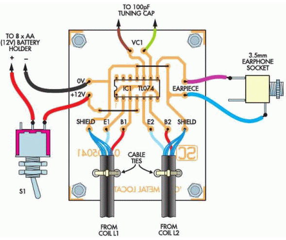
Fig. 1. Schematic diagram - could hardly be easier
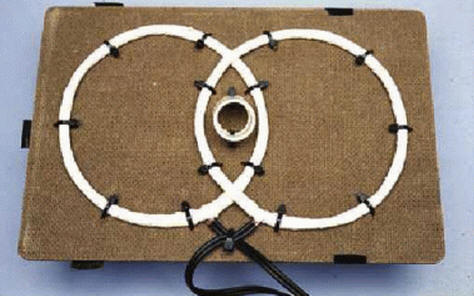
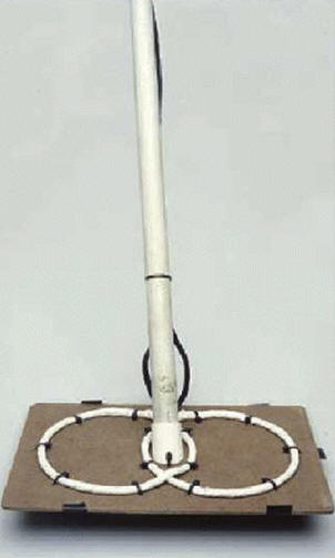
Note to the scheme: each reel contains 70 turns of wire PEL-0,32 wound on a mandrel with a diameter of 12 cm.
The coil should overlap to produce the tone in the headphones.
As can be seen from figure 1, the scheme is very simple. Each generator assembled on a single the amplifier Quad opamps plus search coil!
The signals from these generators are mixed (by type of detectors on the beat) and in the result you can hear the beat signal.
But beyond this similarity with the detectors on the beat is there and difference. And it the difference, which significantly increases the sensitivity of the detector is that each coil modifies the frequency of the oscillator using inductive connection. The result is a "balance" as IB detectors and sensitivity becomes more than the schemes on the beat.
Besides all this, requires a means to control the output frequency of the beating to configure the device. This can be accomplished in different ways, in this case, a standard variable capacitor 100 pF from AM receiver, connected between the two oscillators.
Since the concept of schema derived from induction-balanced and detectors on the beatings, then we will call the principle of operation of this detector "balance of the beats" (BB).
Features
Key features of the scheme are:
- Depending on how it is designed, this detector has potentially sensitivity like IB detector.
- Not needed by the receiving amplifier or detector level, this greatly simplifies the circuit and reduces its cost. The scheme contains only two basic component, with similar sensitivity scheme IB budget will contain about 10..20 components.
- Both search generator are identical, therefore the scheme is resistant to change supply voltage and ambient temperature. Because of this elimination schemes compensation and voltage regulator.
- Each of the coils has the opposite response to the target, and therefore high immunity to mineralization of the earth. At the same time, the scheme has good discrimination at the point of overlap of the two coils.
Scheme
In the basis of design is the simplest generator and the inverter. Consider first generator IC1. Since the inductance begins to resist quick voltage variations (called response), any change in logic level the output (pin 1) will be transmitted to the inverting input 2-delayed time. The slew rate of the output voltage is about 8V/MS, all subsequent switch IC1 respectively delayed and thus the generator enters the operation mode, the steady-state oscillations at the output.
One of the conclusions of the search coil is connected to reinvestiruet input (pin 3), which stabilizes the work. In principle, conclusion 3 could not be left connected, but that would be a suboptimal solution.
Because different integrated circuits have a different slew rate the output voltage and the input resistance, they are unlikely to work in to this scheme. However, TL074CN widespread and its availability should not be problem.
The search coil is a critical part of the generator and it needs to be properly constructed, the generator and earned was received the required output frequency.
This frequency must be large enough, but not so much that it would influenced by noise or instability of the parameters.
The performance of the chip IC1 and the inductance of the coil affect the frequency generation, which is in the region of 260 kHz (without connected screen Faraday). The Faraday screen increases the inductance of the coil is about twice that accordingly, the output frequency of the generator becomes about two times less.
Generator on IC1b included exactly the same way as IC1a, except that it the search coil is connected in antiphase.
As the search coil is moved parallel to the ground, the appearance metal increases the first inductance L1 and then L2, or Vice versa, in the resulting frequency of oscillation is slightly reduced. The third amplifier IC1c used to mix signals from two generators, and at its output it turns out the beat frequency lying in the audio range.
All this is a distinctive feature of the detector BB type. The presence of metal not only changes the frequency of the search oscillator, but just like IB the detector affects the other coil. In fact, both affect each kakuske other through the mutual induction, and it is a cause of a substantial increase the sensitivity of the system.
In addition to all this, you need to find a way to configure the detector. It is achieved by means of variable condenser VC1, which is connected with two inductances (search coils). As VC1 will work almost any variable capacitor, it is desirable only that he would not too large capacity - from 47 pF to 100 pF. If none, then you can use a larger capacitor value, enabling him consistently capacity pF.
As headphones are used mesotheleoma. If the volume too high, then it can be reduced by including in series with the headphones resistor suitable denomination. Inductive sound projector use is not recommended because of the danger of overloading IC1c.
The current consumption circuit is approximately 15mA. Eight AA batteries are enough about 70 hours of work.
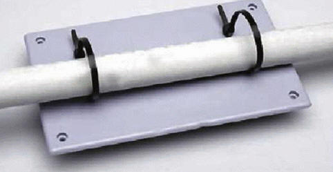
Design
In the scheme there is a large amount of detail, so it's hard to avoid any error. It is important not to be mistaken with the inclusion of a chip and a phasing search coils. In addition, other problems should not be.
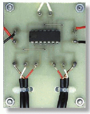
Insert in the printed circuit Board 12 pins and solder them, then solder the two wires leading to the switch. As the pins use thick tinned copper wire.
Now it's time to fill the printed circuit Board. Since this is sensitive, high-frequency circuit, it is recommended to solder IC1 directly, without the panels. After you have inserted the chip, verify proper installation. TL074CN sufficiently reliable chip, solder it as soon as possible that would to avoid overheating.
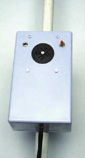
Solder the variable capacitor VC1, the headphone Jack, battery, and switch (observe the polarity - the error might put the scheme out of action). Switch power is normally connected to the positive terminal of the battery. Some batteries have tinned contact, others (such we use) require 9V transitional block for connection. Again, observe the polarity!
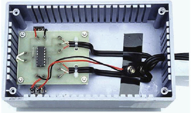
Now attach the power switch and headphone Jack to the body.
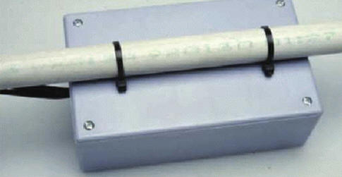
I used long screws to attach VC1 under the circuit Board, it is lightweight and effective way to install an AC condenser in the housing.
Use a piece of non-conductive rubber to isolate VC1 from the PCB.
Author: Thomas Scarborough