


")

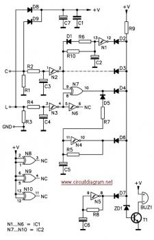
Here is the circuit diagram of car headlight alarm. This device can be set for one or two functions:
First, to indicate that the head lights (or the side lights) should be switched off after switching off the ignition contact. With this circuit, there should be no dead battery due to headlights that were left on.
Second, to indicate that the head lights should be on once ignition contact is switched on.
Components List:
D1,D2,D3,D4,D5,D6,D7 : 1N4148 D8,D9 : 1N4007 ZD1 : 2V4 R1,R2,R3,R4 : 47K R5 : 220K R6,R7 : 470 R8,R9 : 10K R10 : 1M C1 : 100nF C2,C3,C4,C5,C6 : 22?F/16V C7 : 470?F/16V T1 : BC547B IC1 : CD40106 IC2 : CD4070 Buz1 : Buzzer
Car Headlight Alarm Features:
- Continuously repeated alarm tone for lights ON (may be disabled)
- Repeated alarm tone for lights OUT
- Only 3 wires are required for hook-up
This circuit come from Velleman product kit. Download the kit manual of Velleman car headlight alarm from the following link:
 Car Headlight Alarm Circuit 557.34 KB
Download Kit Manual
Car Headlight Alarm Circuit 557.34 KB
Download Kit Manual
You may purchase the kit from electronic online store.