


")

 The problem can be solved using a small external driver stage: two resistors and a transistor mounted on a small piece of perforated board, connected in place of the original LED. The new high-brightness LED is then connected between the output of the current source and a spare motherboard ground connection (for example on the infrared port) or to a grounded screw in the enclosure. R1 is responsible for the constant current. High-brightness red LEDs are driven at 20 mA (R1 = 150 Ω), whereas high-brightness blue LEDs require 10 mA (R1 = 75 Ω). In view of the large number of different PC motherboards available, it is not certain that this driver can be used in every PC. It is easy to check whether the circuit will work: use a DC voltmeter to measure the voltage between the positive connection on the LED (generally a red wire or a pin marked with an arrow on the LED connector) and ground (not the other pin of the connector). If this reads +5 V independent of whether the LED is on or not, then the driver can be used.
Case Modding
The aesthetics of ‘case modding’ (modifying a PC’s enclosure) offer plenty of scope for debate and plenty of scope for original circuits. Low current LED indicators are usually fitted in PC enclosures. Although this certainly saves energy, the LEDs do not light particularly brightly. It is not completely straightforward to replace the low-current types with high-brightness types since the latter draw a current of 20 mA rather than 2 mA. This can - whatever people might tell you to the contrary - in some instances lead to excessive load on the LED drivers on the motherboard.
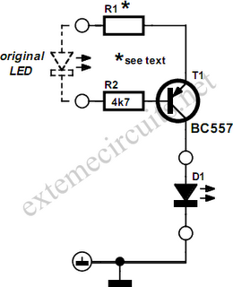
The problem can be solved using a small external driver stage: two resistors and a transistor mounted on a small piece of perforated board, connected in place of the original LED. The new high-brightness LED is then connected between the output of the current source and a spare motherboard ground connection (for example on the infrared port) or to a grounded screw in the enclosure. R1 is responsible for the constant current. High-brightness red LEDs are driven at 20 mA (R1 = 150 Ω), whereas high-brightness blue LEDs require 10 mA (R1 = 75 Ω). In view of the large number of different PC motherboards available, it is not certain that this driver can be used in every PC. It is easy to check whether the circuit will work: use a DC voltmeter to measure the voltage between the positive connection on the LED (generally a red wire or a pin marked with an arrow on the LED connector) and ground (not the other pin of the connector). If this reads +5 V independent of whether the LED is on or not, then the driver can be used.
The problem can be solved using a small external driver stage: two resistors and a transistor mounted on a small piece of perforated board, connected in place of the original LED. The new high-brightness LED is then connected between the output of the current source and a spare motherboard ground connection (for example on the infrared port) or to a grounded screw in the enclosure. R1 is responsible for the constant current. High-brightness red LEDs are driven at 20 mA (R1 = 150 Ω), whereas high-brightness blue LEDs require 10 mA (R1 = 75 Ω). In view of the large number of different PC motherboards available, it is not certain that this driver can be used in every PC. It is easy to check whether the circuit will work: use a DC voltmeter to measure the voltage between the positive connection on the LED (generally a red wire or a pin marked with an arrow on the LED connector) and ground (not the other pin of the connector). If this reads +5 V independent of whether the LED is on or not, then the driver can be used.
- Details