


")

We offer our readers the device is made of modern element base and differs from that previously published in the journal designs advanced features and applications for managing remote control infrared rays.
The described device is intended for indicating the current time, the audible signals at a specified time and temperature display in two locations (indoor and on the street) in the range of -55…+99 °C with an accuracy of ±1 °C. Time and temperature displayed alternately (for 10, 1 and 2 respectively). Installation the clock, time alarm, the alarm is off, damping and the ignition indicator produce with IR remote controller (RC).
The alarm beeps with a pause of 10: first two short (approximately 0.1) single, then the same dual (with a pause of 0.1 s), and after them - two triplex (with the same beat). After triple minutes signals served every second up until the alarm is turned off (such "algorithm" is convenient if in the room the baby sleeps). There is a Snooze function (repeat the alarm after a certain time), allowing more sleep after the first signal. If the indicator is extinguished (for example, at night, so as not to disturb the children while falling asleep), at the time of alarm he ignited and before disconnecting or switching to the Snooze mode shows the current time. Provided a short audio response to pressing buttons on the remote, display the led light of the passage of the commands from the console, backup power in case of voltage (in this case, the alarm emits a continuous signal).
Schematic diagram of the device depicted in Fig. 1. It is based on the microcontroller DD2 ATS [1]. He manages the work of all units. In his includes a nonvolatile program memory (4 Kbytes) RAM (128 bytes), two timer interrupt system, etc.
(click to enlarge)
For a safe start and protect the microcontroller from power failure applied chip CSP (DA1). It holds at its output (pin. 3) low level when the supply voltage is less than 4.7 V. the Capacitor C6 delays the transition to status log. 0 (i.e. the start of the microcontroller) after the voltage power will be above the threshold level. In the extreme case, this chip can not to install, using the standard reset circuit recommended by Atmel. However, the possible failure of your machine in the "gaps" in the food.
The scoreboard consists of five led digital indicators SA08-11GWA Kingbright company. Indication - static. To reduce the brightness in the chain nutrition indicators included diodes VD5 and VD6. When displaying time HG1 and HG2 show respectively the tens and units of hours, HG3 - dash (-), HG4 and HG5 - tens and units of minutes (for example, 22-11), in the temperature measurement mode HG1 indicates its sign (for negative values), a HG2, HG3 and HG4, HG5 - accordingly, the numerical value and unit of measurement (for example, -18°C for outdoor sensor and 23°.With for room, as evidenced by the symbol "." the fourth category).
To control the node display used only three pins of the microcontroller: P1.2 (14) for data transfer; P1.3 (15) for Gating each bit, put on 2 P1; P1.4 (16) to output loaded at DD3-DD7 data on them outputs. Chip NS [2] is an eight-bit register with serial input and parallel output latch. This allows first to upload and download data, and then send them to the output. The outputs can to transfer to the third state. Every pin can give current to 35 mA.
As the clock applied to the chip PCF8583 [3], which allowed to forget the time can be off with no power (accuracy depends almost exclusively from the quartz resonator ZQ1 at 32768 Hz). In PCF8583 is static memory that is used to determine the first power on hours (to prepare and the microcontroller, and the clock itself to normal functioning) and a hardware alarm. The coincidence of the set time with the current on output INT (7) appears low logic level. As a result closes the supply circuit of the electromagnetic emitter 1, and the output of RZ.Z (7) microcontroller DD2 is supplied to the interrupt signal. Further off programmatically the signal from the INT pin and the control emitter goes to the microcontroller (via the electronic key on field-effect transistors VT1, VT2). Controlled watch on the bus l2C, organized programmatically (in the microcontroller does not).
For feeding audio signals applied electromagnetic emitter NSMH company JL World with a built-in oscillator operating at a frequency of about 2200 Hz.
The GB1 battery is used to power the chip clock and sound projector with the loss the voltage in the network. As mentioned, the alarm in this case emits a constant the signal, which can be turned off only by pressing the SB1.
To receive signals from the remote control used integrated IR receiver range SFH506-36 Siemens [4]. This chip is very sensitive to interference on the food chain, so it includes the filter VD4C8C9.
The device is powered by a stabilized voltage Converter based on the chip MS (domestic analogue - CREW). The work of such converters are described in detail in [5]
Schematic diagram of the IR remote control is shown in Fig. 2. It is made on the basis of compact calculator Chinese production in the form of cell phone (used the casing, keyboard and battery, consisting of two elements A). As the transmitter used chip SAA3010 [6] (analog - INA3010D ON "Integral") in the SOIC package. This chip works in the IR Remote control RC-5, developed by Philips to manage household equipment and widespread (used in many TVs, including those produced, for example, ON "Horizon").
In standby mode SAA3010 consumes negligible current, which makes the operation of the remote is very convenient - no need for a separate power switch. The chip goes into an active state when any button is pressed and returns to the mode microparasite when you release it. The number used system code RC-5 - 0 (to control TV). If necessary, for example, so as not to interfere with the TV if it uses the same standard, it is easy to switch to another coding table. Permissible use and ready remote control from any household device, if it is to take care of transcoding commands. To familiarize themselves with the IR remote control RC-5 in the article [7].
As remote temperature sensors applied DS1621 chip firms DALLAS. They are good that is used to exchange interface 12C, which we already generated programmatically. This means that you can connect to the same conclusions microcontroller as the watch. Measurement error is determined entirely sensors and does not exceed ±0,5 °C, and the indication accuracy of 1°C. More detailed information about digital temperature sensors can be obtained on the website [8].
A few words about the location of the sensors. External must be sheltered from direct sunlight and flow of air at room temperature, penetrating through cracks in frames, and an inner position so that it was maximally removed from the heating bodies (radiators, light fixtures, etc.). External the sensor is preferably sealed to avoid corrosion of the PCB and so D. (the author used a silicone sealant). The conductivity of this down but sluggish current processes, such as changes in atmospheric temperature, it is quite acceptable.
The functions of the buttons of the remote control: "TS" - time setting. After pressing enter the time in 24-hour format with trailing zeros, i.e., if at the moment eight thirty in the morning, then 0 8 - 3 0. Making sure the time is correct, press any button and the unit switches to the clock mode.
"BS" - set the alarm time. The procedure is similar the installation time.
"OFF" disables the alarm. Button SB2 in the watch performs the same function.
"LED" on/off indicators.
Pressing any other button when the alarm time the alarm switches the Snooze mode.
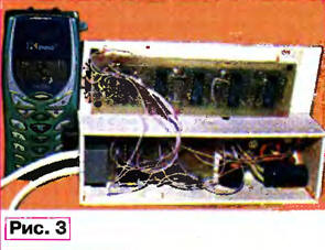
The appearance of the remote control and view of the mounting of the main unit of the device shown in Fig. 3.
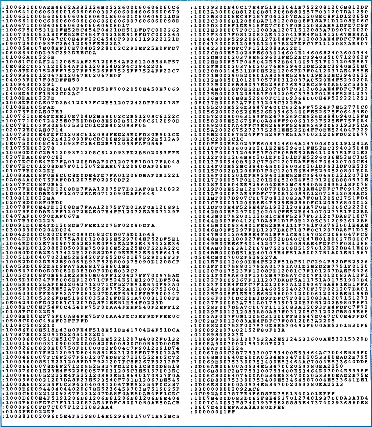
Codes firmware of the microcontroller in the form of a hex file given in the table.
Source text
The program is written in the language C. It provides opportunities for further upgrades. Program developed and compiled in the IDE Keil mVision2 V2.36. Assembler - A51 version V7.04, the compiler - With V7.04, linker - BL51 version V5.02. The project file - termo.Uv2. Detailed description of the compiler can be found at the website [9] (there it is also possible to download a demo version.
(click to enlarge)
The control program recorded in the controller with the help of programmer TURBO. Before programming is necessary to check the conformity of the installation concept device. Properly collected design in building not needed.
Literature
Author: Dmitry Chebyshev, Omsk