


")

These thermometers are constructed in an unusual way in the first one the temperature-sensitive element (thermistor) is included in the integrating circuit, in second in differentiating. Changing the time constants of these circuits under the effect of outdoor temperature thermistor ambient temperature is converted into a change the duty cycle of the rectangular pulses, resulting in changes effective the output voltage of the device, which is registered by the microammeter. Devices made on pervasive digital circuits and available for repetition even novice radio Amateurs.
The temperature-sensitive element in an analog thermometers often include the measuring bridge. Such a temperature sensor has a major drawback, associated with the need to limit the current through the bridge values, excluding the self-heating of its constituent resistors. In addition, are often rather high demands on the stability of the voltage supplied to the measuring bridge. To amplify the signal taken from the bridge, and stabilization applied to it by the tension in many analog thermometers use the operational amplifiers. This complicates the design and establishment of such devices.
From these disadvantages of the free offer of the pulse thermometer. It contains the generator of rectangular pulses, an integrating circuit with temperature-sensitive element, a pulse shaper and a dial indicator registering the effective stress is proportional to the pulse ratio. Most suitable for such a device CMOS digital circuits: they have a low voltage level practically does not differ from 0, and the high - voltage supply.
Schematic diagram of the thermometer shown in Fig. 1.
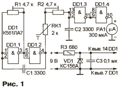
On the elements DD1.1, DD1.2 assembled the generator of rectangular pulses with a repetition rate of about 60 kHz and a duty cycle of 2. From the generator oscillations act on integrated circuit RK1R2C2. Depending on the resistance of the thermistor (the thermistor) RK1 changes the time constant of the integrating circuit and, accordingly, the pulse duration, input of the shaper performed on the elements DD1.3 and DD1.4. The pulse duration at the exit of the element DD1.4 is proportional to the temperature and determines the effective voltage detected device RA1. Rigged resistor R1 is used to set the "zero", R2 - to adjust the sensitivity (it is maximum at its minimum resistance). When the value of the thermistor is not more than 5 ohms, the dependence of resistance on temperature is close to linear in the interval from -20 to +50 °C. the measurement Error does not exceed ±1 °C.
The stability of the supply voltage (and hence the amplitude of the pulses) provides parametric stabilizer elements VD1 and R3. Consumed thermometer current does not exceed 7 mA.
All the parts except the thermistor RK1 and microammeter RA1, placed on a printed the Board, made in accordance with Fig. 2.
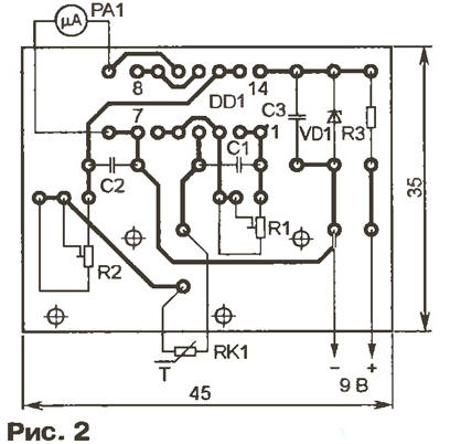
The fee is intended to apply of fixed resistors MLT, wire trimming resistors SP5-3, capacitors km-6 (C1 and C2 is preferably a group M47 or M75). The thermistor RK1 - CMT with a negative TCR. Microammeter RA1 - M4387 or any other current full deflection of 1 mA and an internal resistance of at least 500 Ohms.
When establishing the thermistor is placed in a bath of melting ice and trimmer resistor R1 sets the arrow tool RA1 to the zero mark of the scale. Then the sensor is transferred into water heated to a temperature of +50 °C, and trimming resistor R2 achieve deflection to the last mark.
For temperature measurement in a wider range, for example, from -60 to +150 °C, in parallel with the thermistor resistance R or sequentially with him should to include a resistor 3R or 1/3R, respectively. Sensitivity the device, after such improvements, of course, will decrease, and the error measurements may increase to ±3…5 °C. If you need higher precision, the specified range of measured temperatures should be split into two or three sub-band and to carry out the linearization of the thermistor in each sub-band. In this case measurement error can be reduced to ±1 …1,5 °C.
The TTL chips that hook up, compared with chips series CMOS logic levels differ significantly from the ideal values. In addition, the basic elements chips these series very significant input currents. Therefore, the thermometer on such chips should be collected according to the scheme shown in Fig. 3.
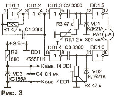
Vibrations of a rectangular shape with a repetition rate of 60 kHz is generated the generator on the elements DD1.1, DD1.2, are fed to the inputs of buffer elements DD1.3 and DD1.4. They eliminate the mutual influence of the differentiating circuits and C2R3RK1 C3R4 and reduce the load on the generator, which is beneficial to the stability of its frequency. The element DD1.6 generates the sequence in which the pulse duration is determined by the "exemplary" differentiating circuit R4C3, a DD1.5 - the sequence in which it depends on the resistance thermistor RK1 included in measuring the differentiating circuit RK1R3C2. In the result of using the device RA1 flowing pulsating current, the effective value which is proportional to the ambient temperature. For component values differentiating circuits, indicated in the diagram, the diodes VD1, VD2 can be eliminated. However, if you use smaller resistors of the values of the capacitors C1 - C3 greater capacity to protect the inverters DD1.5, DD1.6 from breakdown of these diodes necessary.
In the thermometer use parts from the same type as that of the preceding. Instead K555LN1 acceptable use chips KLN, K155LNZ, K155LN5, KLN. Diode KDA you can replace it with another diode in this series, and the series KD522.
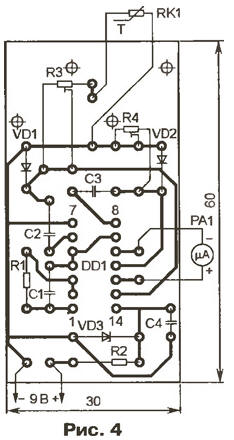
All the parts except the thermistor RK1 and microammeter RA1, placed on a printed Board (Fig. 4). Setting of the thermometer is to install a resistor R3 the maximum temperature, and resistor R4 is zero. In the temperature range from -20 to +50 °C measurement error does not exceed ±1 °C.
This thermometer can measure body temperature. Previously the device must be calibrated in the range of +36. ..+40°C. the thermistor is placed in heated to 36 °C mineral oil and a trimming resistor R4 set the arrow of the microammeter to the zero mark of the scale. Then raised the oil temperature up to +40°C, the resistor R3 sets the arrow on the last the division of the scale. These operations must be repeated two or three times for better reproducibility of the measurement. (When calibrating this instrument to use mineral oil and not water, because of the high the electrical conductivity of aqueous solutions the results of the measurements significantly distorted).
After calibration, the thermistor is placed in a glass tube, sealed on the one hand, and filled with epoxy resin. Such a sensor design eliminates the error in the temperature measurement caused by electric the contact of the thermistor with the patient's skin.
In the temperature range from +36 to +40 °C temperature dependence of resistance thermistor is almost linear. When using as a C1-C3 thermostable capacitors (for example, mica or Teflon) measurement error in this interval will not exceed ±0.1°C.
Author: I. Tsaplin, Krasnodar