


")

The instrument is designed for accurate measurement in a wide range of temperatures of different objects and can be recommended for use both in everyday life and in technology. Unlike previously published similar devices, this thermometer used ENCORE series K, so it contains a relatively small number of elements. The thermometer is ready to use immediately after power-up. But, unfortunately, the lack of serial sensors with low thermal inertia leads to a considerable duration of the measurement process (about five minutes), which somewhat limits the scope of application of the thermometer.
Main technical characteristics
The limits of the measured temperature, °C
-50…+99.9
The basic error of measurement, °C
±0,1
Additional error, °C:
from the change of ambient temperature within 0 to +40 °C
±0,05
from the change of sensors
±0,1
Maximum length of shielded cable for the connection of sensors with device (the resistance of each wire in the cable is not more than 5 Ohms), m
300
Power consumption, W
3
Dimensions, mm
120X H
Structural diagram of the digital thermometer shown in Fig.1. The temperature change of the object, where the sensor causes a change in resistance of the sensor, which in the block E1 is converted to a corresponding voltage change. The inverter U1 is powered by the current stabilizer G1. The output signal of the block E1 is amplified by the amplifier A1, and is supplied to an analog-to-digital Converter (ADC) U2, the output of which includes a digital display unit H1, elucidating on the current temperature of the controlled object.
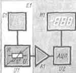
Structural scheme
Switch SB1 (see circuit diagram) choose one of the temperature sensors RK1, RK2, installed on the object, the temperature of which is to be measured. The sensor is incorporated in one arm of the measuring bridge DC, made with precision resistors R1 - R5. The accuracy and linearity of the indicator within the measured temperature is determined mainly by the stability of the current supply of the measuring bridge.
Schematic diagram (click to enlarge)
The stabilizer of the supply current of the bridge is performed by operational amplifier DA1.2. Trimmer resistor R11 allows you to slightly change the value of the output current, which allows you to change the steepness of the conversion of the resistance of the temperature sensor to a voltage and provides the installation of the upper boundary of the measured temperature. The bottom border set the trimming resistor R1.
The voltage from the diagonal of the measuring bridge, is proportional to the temperature, is amplified by the differential amplifier realized by operational amplifier DA1.1, and its output is fed to the ADC input. Capacitors C1, C2, C4 are used to filter out noise.
The ADC is implemented on BIS CPA and works on the principle of double integration with auto adjust "zero" and the automatic determination of polarity of the input signal. A signal that carries information about the current temperature of the selected object presented at the ADC output in a form suitable for display semielemental indicators. He comes on Board, consisting of three LEDs HG1 - HG3 and LEDs HL1.
Led lights at negative temperature of the measured object. To divide whole numbers and tenths of a degree on the indicator HG2 is displayed by a comma.
Powered thermometer from the mains AC voltage of 220 V through the transformer T1. To stabilize bipolar supply voltage is provided by parametric stabilizers VD1R18 and VD2R19. Exemplary voltage for the ADC and the current stabilizer removed from the voltage divider resistors R16, R17. It is additionally filtered by a capacitor C12.
All the elements of a digital thermometer placed on two printed circuit boards (see Fig.3 and Fig.4) connected by corners.
The drawing of the main Board
Drawing extra cost
The device uses fixed resistors R2 - R5 - S2-29V-0,125: R18, R19 - MLT-0,5; trimmers - GPA-38, other - MLT-0,125. Capacitors C1 - C5, C9 - K73-17-C7, C10, C11 - CT.1; C6, C8 - K10-7; C12-14 - C50-6.
To ensure interchangeability of sensors while maintaining the specified accuracy of the used commercially available resistance temperature detectors SCI-6114 GOST 6651-72 with a nominal static characteristic gr.23. In the absence of standard sensors you can make them yourself. For this it is necessary to measure 619 cm wire PETV diameter of 0.05 mm. reel it bifilar on an insulating mandrel, to one end of the sensor wires to solder one flexible output, the second two the same conclusion.
You can solder the sensor directly to the conductors of the supply cable. Each sensor will require three conductor in the cable. Such connection allows to compensate the temperature error introduced by the conductors of the cable.
Further, manufactured housing, able to work in the environment where the sensor will be installed, fix the mandrel with the winding and filled with epoxy resin. The resistance of the sensor at a temperature of 20 °C should be 57, 52 Ohms.
The power transformer to reduce the size made of four magnitoprovodov,5X12,h (cross-section of about 3 cm kV). Winding I has 3000 turns of wire sew-2 0,08, II - J turns of wire sew-2 0,18, 111 - 70 turns of wire sew-2 of 0.4. The power transformer may use a magnetic core, however, the height of the thermometer would have to be increased.
Chip CUT can be replaced by CAD with the respective correction circuits: CPA - CRUA, but will have to change the pattern of the conductors of the circuit Board, while increasing the margin of error of ±0.3 °C can be used CPU with any letter index.
Accurately assembled from known-good elements of the thermometer does not require establishing, it is only necessary to establish the limits of the measuring range. To do this, instead of a sensor include its equivalent (store or precision resistors resistor). First, include the resistor 41,7 Ohms, and resistor R1 sets the scoreboard reading minus 50 °C, then replace the resistor with a nominal value 75,59 Ohms, and resistor R11 sets the reading plus 99.9 °C. a calibration Operation should be repeated twice.
If you need to extend the interval of the measured temperature to 180°C need to be connected to another ADC digital indicator ALSB. Other specifications of the thermometer are retained.
Authors: N. Homenkov, A. Zverev, Orel; Publication: N. Bolshakov, rf.atnn.ru