


")

The optimum tip temperature of soldering iron - an essential condition of obtaining quality soldering. In Amateur practice this is of particular importance, so as when mounting the electronic device, the designer must to use the same soldering iron with interchangeable tips, significantly which differ in their thermal characteristics. The use of different solders, the brand of which is often unknown, also requires experimental selection the temperature of the soldering tip. The author of the article analyzes the effectiveness of regulators power, familiar to radio Amateurs for publications in our journal, and offers to repeat his version of the temperature controller heating soldering iron digital.
A method of controlling the heating of a soldering iron [1], when its power is regulated only in working order (the soldering iron is on the stand) and in a working capacity is 100%, gives positive results only with a non-replaceable tip. Amateur radio practice shows that good results can be achieved separate operational control of the power of the soldering iron in the working and standby modes. This method is even preferable singlemode accurate stabilization the temperature of the sting, since it allows a compromise between the permanent the maintenance of soldering iron in standby for many hours and wear the working part of the sting due to the dissolution of copper in the solder.
Currently settled some, "Amateur radio is standard on the average power regulators for thermal devices [2]. Its essence lies in that the regulation is carried out by pulse width method, opening power SCR or triac in the moments close to the transition network voltage through zero. It is often called the method of "quiet regulation". The use of CMOS chips gives a simple circuit solution for the formation of the pulse width of the signal. Its disadvantage is the vagueness of the generator in the final positions of the engine driving resistor and the need for the marking of the scale capacity. These shortcomings device freely [13], which used digital the principle of formation of the pulse width signal. It is especially useful in the formation of a multi-mode power control soldering iron because it does not contain elements that require configuration when switching modes.
The scheme of such options digital power control soldering iron shown in Fig. 1. As the base solution used triac controller described in [4]. In the power source circuits added led NO signaling the unit is connected to the network. This Addendum was as if "free* - the led is powered by a wave of the mains current, recharging the quenching capacitor C1, directly to power the device is not used. The average current through the led" does not exceed 15 mA. When changing the polarity of almost all reverse voltage, equal in value to the sum of voltage stabilization Zener VDZ and the direct voltage drop across the diode VD2 applied to the diode VD1, reverse resistance of which is considerably higher than that of the led.
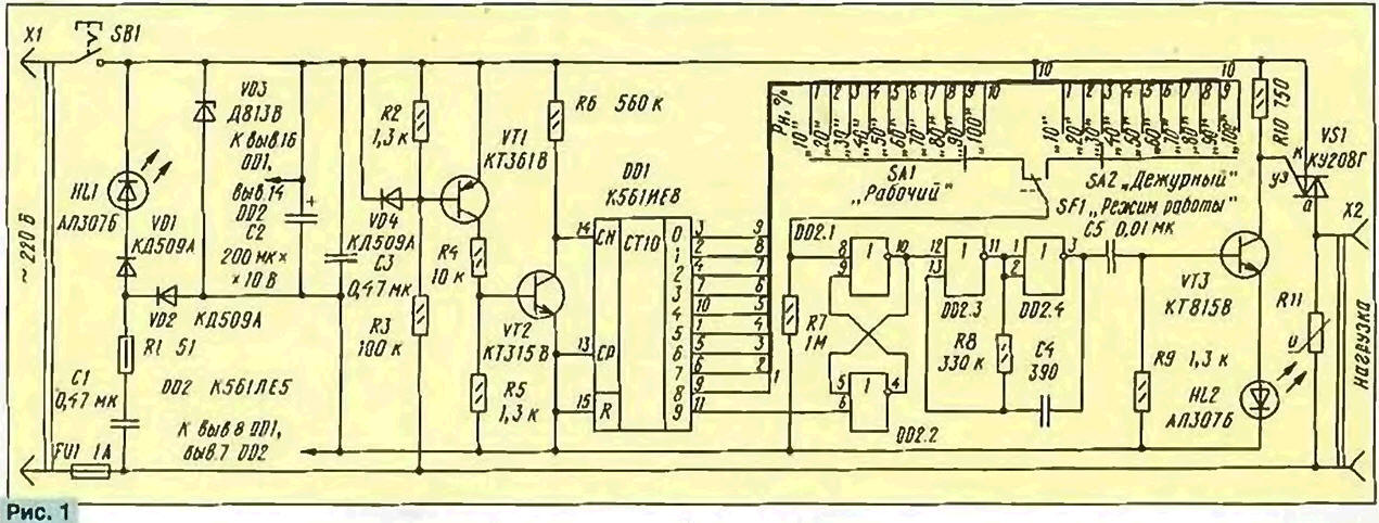
(click to enlarge)
If the device is used at an elevated temperature, increasing the reverse current of the diode VD1, to protect the led from reversed voltage it shall be shorted by the resistor 1…3 kOhm.
Transistor VT1 is used to highlight the moment of transition of the mains voltage using "zero". Diode VD4 protects the emitter junction of this transistor from of the half-wave reverse voltage. The VT2 transistor inverts the signal taken from the collector of the transistor VT1, increases the steepness of the front that allows you to submit it directly to the input of the JV decimal counter DD1 without any additional shapers.
The front of the counting of the pulse at the input circuit is formed at the end of each positive (relative to the lower scheme power cord) halftime voltage. The outputs 0-9 counter with built-in decoder, there is a "running* the high signal (log. 1). When the signal this level occurs at the output 9 (pin 11) of the counter, RS-trigger, assembled on the elements DD2.1, DD2.2, is set to be a high level the output 10 of the element DD2.1, which prohibits the operation of the pulse generator start triac VS1. The generator is made on the elements DD2.3, DD2.4. In this state the load regulator is de-energized. The inclusion of the load in the network will occur after switch RS-flip-flop to the opposite state signal at a high level the output 8 of the element DD2.1.
The time of arrival of the pulse cycle of the load relative to the pulse off is determined by the output number of the counter connected to the output 8 of the element DD2.1. Thus, the power supplied to the soldering iron in the operating mode and the mode expectations, determines the position of the contacts of the switches SА1 and SА2 respectively. Change the modes by switch SF1 clicking on its button the rocker, holding the soldering iron on the stand. In both modes the power from 10 up to 100% in 10% increments set switches SА1 and SА2. The Resistor R7 eliminates the uncertainty of the signal at the output 8 of the element DD2.1 when shifting.
In the working periods of the network pulse generator start triac \/S1 works continuously, which allows you to turn on the triac with resistive load 60W when the voltage of about 20 V. a Visual estimate of the relative power delivered to a load by light НL2. Although through it and pass current pulses of the control electrode of the triac value in several tens of milliamps, the average current is the unit of milliampere. Since the regulator output DC component of the signal is close to zero, when certain restrictions, you can manage power low-voltage soldering irons, included in the network through a step-down transformer. The restrictions associated with the feature of transformer operation. If the load of the transformer is disabled., to the output of the controller is connected to a high-q coil inductance, on which there are voltage spikes that are almost equal to twice the amplitude voltage of about 600 V. This mode is extremely undesirable, therefore, to ensure the safety regulator at random switching load controller output is shunted by the varistor R11 dot salient features 350…300 V. But if the regulator will only be used with an active load, a varistor can be eliminated.
The second limitation is associated with transients in transformers, due to their low operating frequency. When the transformer is in the network (even at zero voltage), the first half is spent on primary the magnetization of the magnetic circuit, accompanied by increased primary current winding. For example, for popular the soldering iron APSN 25/24 (GOST 7219-83), connected to the network through a transformer, the amplitude of the current pulse was 2.5 And that is 12 times greater than in the steady state. The value of amplitude of a current the second half-period exceeded the steady-state value of approximately
50% and for the third half-cycle is about 10 %. Therefore, to include even loaded the transformer is preferably as little as possible. This is due to use to control the power of the integer number of full periods that, with the one hand, provides a near-zero value of the constant component, and a compromise between thermal inertia loads, easily implementation and minimizing the number of switching of the load per unit time.
At the time, our industry produced low-voltage soldering irons powered from the network via the quenching capacitor built in a plastic case, similar in the size of the transformer unit of the same capacity. These soldering irons to connect to the regulator cannot. But if that happens, from the failure of the regulator will protect the fuse FU1.
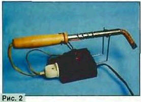
The appearance of a controller shown in Fig. 2, and the layout and Assembly of its parts - on Fig. 3. It is made in the form of a stand for the soldering iron (used plastic housing from the uniform supply of household radio equipment), Most of the detail is placed and mounted on a universal PCB.
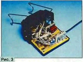
The soldering iron is placed on two metal rack stand, bent steel wire diameter 2.5 mm. nose strut is movable, its mechanical rocker is connected with a push-button switch SF1 (MP1-1). Switch SW (pressure type from table lamps), switches SА1,SА2 (MPN-1) and the LEDs НL1,HL2 placed on the upper cover of the device. Since the position of the contacts switches SА1 and SА2 uniquely determines the power delivered to the load, the led only need HL2 for overall control operation of the device, therefore, if desired, can be deleted.
If the acquisition of small-sized multi-position switches difficult they are replaced by double row socket part multipole connector, using as the movable contact single holder, soldering to it fine a flexible wire. To avoid contact with the mains supply, it is better to use connector with recessed sockets and disconnection of the movable contact of the switch SF1 to include a resistor 91 …100 kOhm.
The regulator is designed to power loads up to 150 watts, so the triac can to operate without heat sink. To reduce the size and to facilitate the layout the parts of the device, you can use miniature triac TC-106 in plastic casing installed on an aluminum lever heat sink area the surface of 10 cm2.
Literature
Author: P. Polyansky, Moscow