


")

This device, built on the ATmega8 microcontroller, may be configured as a thermometer or a thermostat independently for each of the two channels. There is a possibility to set the temperature, turn off the heater in the range from +5 to +95 °C, the temperature difference between the his off and on from 0 to 4 °C and to compensate for the systematic error of temperature sensors from -2 to +2 °C. the Diagram of the thermometer-thermostat shown.
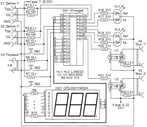
Two sensors DS18B20 connected to the connectors X1 and x2, and the numbers of nests correspond to the numbers of their findings. Used three-wire connection scheme. Many times I was convinced that the only way to achieve the maximum length of the connecting wires, and wherever possible, try to avoid parasitic power sensors. When copper wires 0.5 mm2 cross-section stable the connection is achieved at a distance of 40 m. the sensors are displayed on HG1 - three-digit led display with common anode LEDs each digit. Two-color LEDs HL1 and HL2 show the status of each channel. The control signals to heaters in the mode of the thermostat are formed at the outputs of the microcontroller RV (first channel) and RV7 (the second channel). The two-position control; heater on or off.
For galvanic isolation of the device from actuating devices installed optocouplers U1 and U2. In my case the connectors X4 and X5 are connected to the control circuit of the two triacs VT, switching the heating elements. If necessary, the optocouplers can be replaced by transistors, including in the collector circuit of the winding of the electromagnetic relay. Within 4…5 after the filing of the instrument of power that initializes the sensors and start collecting their evidence. At this time, alternately blink all the elements of the indicator HG1. Next, set the mode to measure and display temperature. In this mode, the heaters are turned off. The sensors on the display alternating with a period of 5 s. If the temperature measured by the sensor connected to the connector X1 led lights HL1, and is connected to the connector x2 - HL2. In this case, if the corresponding channel is configured as thermometer, light color yellow, as if the thermostat, when you submitted the request to activate the heater it is red, and in its absence - green. After clicking the button SB2 readings are displayed only the first sensor, and after clicking on the SB3 is only second. If any sensor is not connected, the circuit is broken, the circuit or the temperature went beyond the 0,1…99,9 °C, the indicator instead of the temperature value appears "Err", and the corresponding heater is switched off.
If during the display of the temperature measured, for example, the first sensor several times to press the button SB2, with each press of the corresponding channel will move from the mode of the thermostat in the thermometer mode and back. When you short press the SB1 is recovering mode alternately display the temperature of two channels. But if you hold the button SB1 is pressed for a long time, thermometer-thermostat will enter the setup mode of the channel, while displaying the temperature of which button was pressed.
In this mode the buttons SB2 and SB3 choose the desired option:
ut1 (ut2) - setting the temperature turn off the heater in channel 1 (2);
dt1 (dt2) -installation temperature difference switch-off and switch-on of the heater in channel 1 (2).
For example, when setting temperature off 35 °C and a difference of 1.5 °C warming will happen to the temperature of 35 °C, it reaches the heater will be switched off and on again when the temperature drops to 33.5 °C. the Optimal choice of the difference reach a compromise between the accuracy of temperature and frequency switching of the heater.
CO1 (CO2) - adjustment of the sensor 1 (2). The entered value is added (considering the sign) of these readings before they will go for further processing. This allows to compensate possible error of the sensor. In the case of repeated short presses on the button SB1, the indicator displays stored in the memory of the microcontroller, the value of the selected parameter, then the buttons SB2 and SB3 (respectively decrease and increase of 0.1 °C) set its new value. Holding down these buttons, the parameter change begins to happen faster (about 10 times per second). 5 seconds after the last pressing of any key the set value is memorized in the nonvolatile memory of the microcontroller, and the indicator displays the current temperature. The program codes from the file Termo2ch.hex record in program (FLASH) memory of the microcontroller, and the information from the file Termo2ch.the epp in its EEPROM. Level configuration of the microcontroller is programmed in accordance with the table.
Discharge Val. Discharge Val. BODEN 0 SKCEL0 0 BODLEVEL 1 SKCEL1 0 BOOTRST 1 SKCEL2 1 BOOTSZ0 1 SKCEL3 0 BOOTSZ1 1 This fuse 0 CKOPT 1 SUT0 0 EESAVE 1 SUT1 1 ON 1 WDTON 0To protect against a runaway program in the microcontroller must be enabled watchdog timer. Since the 1-Wire interface used by sensors sensitive to the clock frequency of the microcontroller, the necessary fine tuning its internal oscillator at 8 MHz. To do this, by connecting the instance of the microcontroller to the programmer, to read the calibration constant, located in the high byte of a word located at address 0x0003 signatures of the microcontroller. After you download the resetter file Termo2ch.epp, but before programming, this constant record a zero in the cell buffer EEPROM programmer. The microcontroller ATmega can be replaced with ATmega8L When replacing the indicator CPD-05211SR2/A similar another type may have to pick up the resistors R8-R15 to provide acceptable brightness.
Download the program of the microcontroller
Author: I. Kotov, Krasnoarmeysk, Donetsk region, Ukraine; Publication: www.cxem.net