Household portable and stationary electric stoves for stoves power control use heater with multiple switched switches spirals. Such heaters and switches out frequently system. More reliable integration heaters, but their power is adjustable as unreliable regulators with a bimetallic plate. To improve the reliability of electric stoves, it is advisable to install them in integration heaters and triac power control. A regulator of this type for the hotplate with two burners or for two individual tiles described in this article.
Triac and trinistorny the power regulators, working on the principle of submission inertial load multiple half-cycles of the mains voltage with the subsequent pause, annoying shortcomings inherent: when working with a powerful load they cause the flashing of lamps included in the same network. This is especially significantly, if such controls are simultaneously fed by a few powerful energy consumers. To reduce the flashing lights maximum possible increase in the frequency load switching and making them the inclusion of anti-phase.
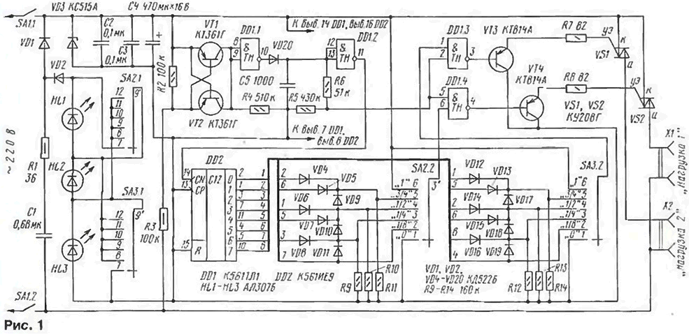
A diagram of the power controller shown in Fig. 1. It is powered by half-wave rectifier diodes VD1. VD2. The function performs firefighting the capacitor C1. a voltage regulator is a Zener diode VD3. Posledovatelno with diode VD2 included a chain of LEDs indicating operation of the controller. This incorporation provides a high brightness of the glow is almost without reduce the maximum current delivered from the power node to the load.

(click to enlarge)
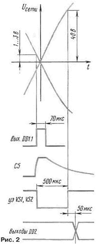
The VT1 and VT2 transistors and resistors R2 - R4 form a chain of formation of pulses in the moments of transition of the mains voltage through zero. Such a device is described in article L. Tyshkevich "Triac switch" ("Radio". 1994. No. 9. S. 36.37) and the article author of "Triac power controllers" ("Radio". 1996. No. 1. S. 44-46). The resistors R2, R3 are selected so that the duration these pulses are small, only about 70 μs (Fig. 2, a diagram of voltage for illustration not to scale). The generated pulses arrive at the input element DD1.1. At the output they have a positive polarity and charge the capacitor C5 is almost to the supply voltage. At the end of the pulse the voltage on the capacitor C5 decreases exponentially. Threshold off elements DD1.3 and DD1.4 (AND-NOT) it reaches approximately 450 microseconds. After the pulse at the exit of the element DD1.1 DDI element.2 switches another 50 µs later.

If the second inputs of the elements DD1.3. DDI.4 with the switches SA2.2 and SA3.2 voltage is a logic high, the pulses pass through these elements and reinforced by the current of the emitter follower transistors VT3 and VT4 go next to the control electrodes of the triacs VS1 and VS2 and open them. The current amplitude of the control pulses is more than 100 mA. full duration - more 500 microseconds. they start about 30...50 MS to the moment of passing network voltage through zero. Such pulse parameters ensure the inclusion triacs series CW without the need of selection. The inclusion of the triac occurs at the beginning of halftime when flattening its volt-ampere characteristics, whereby interference with the radio missing.
The passage of impulses through the elements DD1.3 and DDI.4. manages the node comprising the counter-decoder DD2. diodes VD4 - VD19 and switches SA2 and SA3. The counter-decoder DD2 is switched with a frequency of 100 Hz the decay of pulses of low level, which sends to it from the output of the DDI element.2. This occurs as stated above, after about 50 μs after the pulse the control electrodes of the triacs VS1 and VS2. Diodes VD4 - VD19 form multi-stage Peltier elements OR to form such a sequence of half-periods the inclusion of loads, in which the frequency of their switching maximum and they work, if possible, in different half-cycles of the mains voltage.
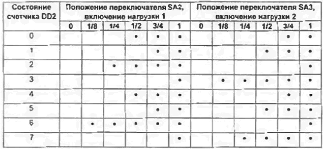
In table dots indicate the status of the counter DD2 (conditional rooms half), which included loads 1 and 2 in accordance with the provisions switches SA2 and SA3.
As a result, the maximum loads are separated in time, what are some reduces losses in the lead-wires. Reduced and so is barely visible because of a sufficiently high switching frequency (12.5 Hz or more) flashing lights included in the same lighting network.
LEDs HL1 and HL3 indicate the inclusion of the relevant loads. If none from loads not included, bright led HL2, Recalling the inclusion of the regulator in the network.
In the power control switches used PH-9-PN (SA2 and SA3), the fit and any other similar contact with groups and dimensions. Chip CTL interchangeable on CRT, KTM - KTM. Instead CIE you can apply KIA, but at the substitution output 8 (pin 9) of the new chips should be connected with its input R (pin 15). unplugging its output 8, for ensure the multiplier 8.
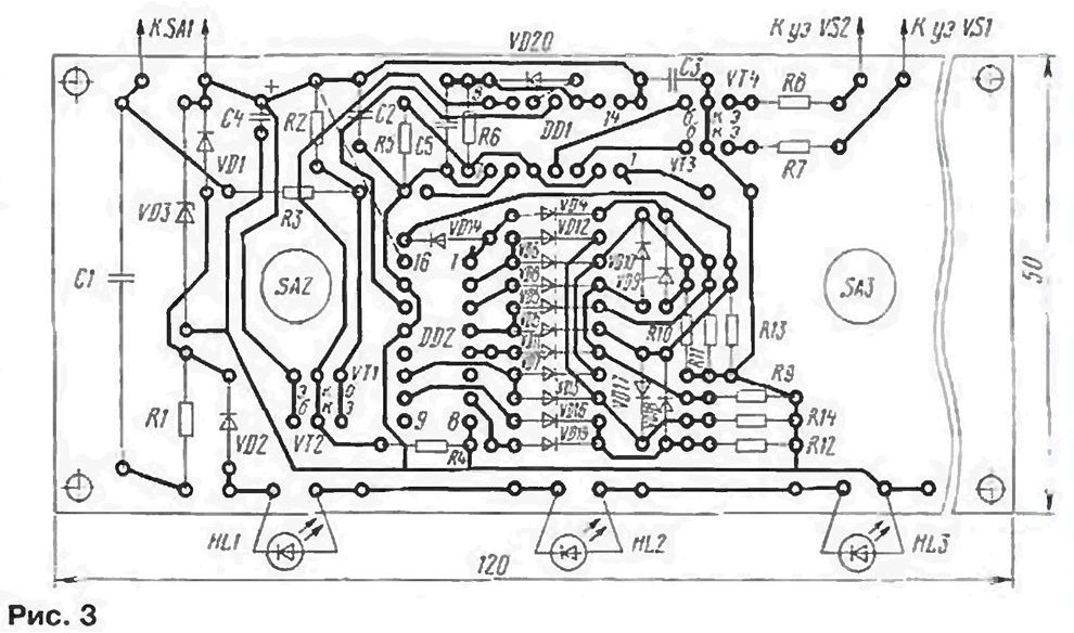
All elements of the regulator except the triac VS1, VS2. output jacks XI. X2 and switch SA1. mounted on the PCB size 50x120 mm (Fig. 3). The fee is designed to install the resistors MLT, capacitor K73 - 16 (C1), import analog capacitor K50-35 (C4) and capacitors km-5 (C2, C3, C5). Diodes VD1. VD2 - pulse or any silicon rectifier, Zener diode VD3 - for a voltage stabilization 13... 15 V. the Transistors VT1 and VT2 can be any silicon thin structure p-n-p. the transistors VT3 and VT4 - average or high power same structure with allowable collector current of 150 mA.

(click to enlarge)
LEDs you can use any, including colorful. Should to pay attention to their installation - they should be as to the extent allow conclusions) outside Board and directed in the same direction as that of axis switches.
Triacs COG (or COW) mounted on finned heat sinks dimensions 25x50x60 mm.
Board, heat sinks with triacs. two pair of jacks and the switch SA. (TV 1-2) placed in a plastic box the size of 70x95x150 mm fee is located as close to the bottom wall of the box, the heatsink - to the top (this wall 70x150 mm). In the lower and upper walls of the drilled hole 42 6 mm diameter with a pitch of 10 mm LEDs and the axis switches withdrawn through the openings in the front wall of the box. Axis and mounting screws with plastic handles switches must not be accessible to accidental contact.
If you use good components and no errors in the installation the regulator does not require establishing. If it doesn't work immediately, can recommend the following procedure for Troubleshooting. Disable the triacs and shorted the findings of the resistor R2. Between a winning output capacitor C4 and right under the scheme the findings of the resistors R7 and R8 to turn on the led of any type (plus - to C4). Nothing without disconnecting from the element DD1.1, turn it into pulse generator the frequency of about 1 Hz. soldered between pins 9 and 10 resistor 100 ohms, and between pins 7 and 8 - oxide capacitor capacitance of 10 μf, for a voltage not less than 16 In (positive output to pin 8). To short-circuit the terminals of the capacitor C1 through the resistor 510 Ohm resistor (0.25 W) to connect to the network inputs of the controller (Fig. 1) the DC power voltage 22...24 V. In this case the positive output of the power source needs to be connected to upper circuit on the wire. Next you should make sure to the correctness of the LEDs HL1 - HL3 at different positions of the switches SA2 and SA3.
With a voltmeter or indicator logic levels to check availability the pulses at the outputs of the counter and DD2 engines switches SA2.2 and SA3.2, and also the passage of pulses through the elements DD1.3, DDI.4 and emitter follower on transistors VT3 and VT4 on included extras LEDs in accordance table.

In the presence of an oscilloscope frequency generator is better to install approximately 1000 Hz, soldered to the element DD1.1 capacitor 10 to 0.01 UF, but additional LEDs in this case it is necessary to connect in series with the resistors 2.2 kOhm.
If after such verification and restore scheme the device is not working, faulty or chain forming pulses VT1, VT2, R2, R3, or triacs.
Author: S. Biryukov, Moscow


