I have made a large number of detectors microwave field is a different design and after the article in "RL" N 11/92, decided to share its experience in this area.
First, in the mentioned article, there are two annoying inaccuracies. First - the value R24 - 820 Ohms, the second in the text nowhere States that the cathode VD1 connect the screen of the signal cable ground directly at VT1 (for reduce the interference on the bus "earth").
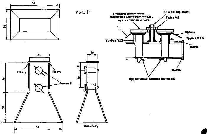
The microwave head is complicated to repeat at home, because you need turning and milling operations, so it is better to make a horn antenna (Fig. 1). It is easier and does not need scarce PTFE. The waveguide and the horn can be run from thin copper or tinned sheet metal. You can use foil glass fiber pre-polished foil and then cover it spinocerebellum flux (not oxidized).

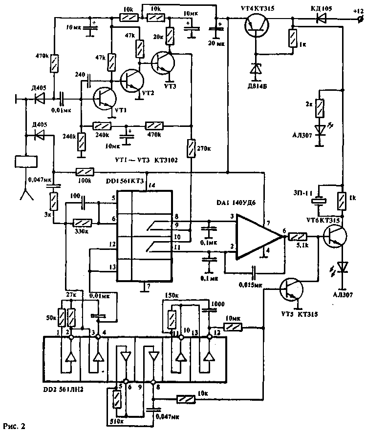
Right under the antenna mounted Board with details. Processing schemes, there is very a lot, but I recommend shown in Fig.2, which requires no adjustments and is not has the setting items.

In conclusion, I want to warn about the need for careful handling of the microwave diodes. They are afraid of static electricity and the breakdown the sensitivity of the microwave field decreases an order of magnitude or more. The cunning of the situation in that when checking the tester punched electrostatics diode behaves exactly as well as serviceable. Therefore, when working with microwave diodes need to follow the same precautions that you would with MOS transistors.
Author: Yury Ignatenko; Publication: www.cxem.net


