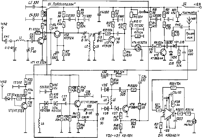
The device is designed to detect electronic bookmarks in the frequency range 65-410 MHz, the approximate determination of their operating frequency and listening on a standard FM receiver (88-108 MHz).
Usually a control device of eavesdropping devices have a very wide bandwidth control, a component of hundreds of megahertz, which reduces their sensitivity and detection range of up to several tens of centimeters. The proposed device has a relatively narrow scanning over a range of frequencies frequency response on the order increases its sensitivity compared with broadband devices, and has the capability of listening to "suspicious" frequencies.
The working principle is based on the indication of the level of electric field intensity bookmarks when deleting or approximation detection devices to them. The radiation level of eavesdropping devices is evaluated by the built-in indicator.
The detection device consists of two amplifiers, one of which in conjunction with filter provides control in the first sub-band 65-155 MHz and the other from 155 MHz to 410 MHz in the second subrange. The first amplifier is assembled on the VT1 transistor with an input filter C1,L1,C2 (Fig.1) to filter out image frequencies above 155 MHz. Both amps are connected to the mixer transistor VT2 and can only work in turn - each with its own local oscillator. Heterodyne working with the first amplifier, assembled on the transistor VT8. It covers the frequency range from 155 to 245 MHz.

The second lo is assembled on the transistor VT7. He works joint amplifier transistor VT6 and covers the range from 345 to 500 MHz.
The mixer transistor VT2 loaded to a bandpass filter C12, L2, C13 L3 with an intermediate frequency (90±5) MHz. Thus, by the first local oscillator control is provided in the first sub-band of frequencies from 65 to 155 MHz, and the second in the second sub-range from 155 to 410 MHz. The sensitivity of the device is regulated by the resistor R15. The attenuator transistor VT4 allows adjustment of level by more than 25 dB. Proyektirovanii detector VD1, VD2 signal is supplied to the operational amplifier DA1 and further to the level indicator. The antenna input of the receiver is connected through a resistor R24, reducing the sensitivity to the VT5 collector.
The scale of the variable resistor R23 is calibrated for both the first and second sub-bands on the high frequency generator.
All parts of the device small-sized. Coil L1 is frameless, with an internal diameter of 6 mm, has 5 turns of wire sew 0.7 mm. Coils L2, L3 wound on a polystyrene frame rigged with cores made of ferrite NN diameter of 2.8 mm and a length of 14 mm, with 10 turns of wire PELSHO 0.15 mm. Coils L4, L5-frameless, with an internal diameter of 6 mm and a step of winding 1 mm, we have: L4 -4 revolution and L5 - 6 turns of wire sew 0.7 mm. Coil L6 L5 wound on top, has 2 turns of wire sew 0.5 mm.
The device configure the device for measuring the frequency response, for example X1-42. Originally set up bandpass filter C12, L2, C13 L3 at the center frequency of 90 MHz with a bandwidth approximately equal to 5 MHz. If in your area there is a station that has a significant level of the signal in this range, it is better to choose a different center frequency in the range of 88 -108 MHz or narrow the bandwidth of the filter.
Further configures the first and second local oscillators. Modifying the parameters of the coils and modes of operation of the transistors at a constant current, ensure the frequency response of the filter is smoothly moved in the first range 65 MHz to 155 MHz, and in the second the range from 155 MHz to 410 MHz. The last tune the filter C1, L1, C2 so that the signal level of the mirror channel was 15 to 20 dB less than the main channel.
The operation is as follows. Originally resistor R15 sets the maximum threshold of "spyware". Next, gently rotating the handle of the resistor R23, control indicator PA1 level signals at first in the first, and then in the second subrange. If a radio station or a "bug", then the meter needle will deflect. Further, changing the position of the device in the room, watching the change of the level indicator. If you are running radionuclide, the reading would be significantly dependent on the spatial orientation. More precise control is performed by the receiver, which is arranged within the intermediate frequency of the device (90±2,5) MHz.
Publication: www.cxem.net


