


")

The proposed device allows using a conventional switch with one pair of contacts to control a chandelier with four lights, including one, two, three or all four.
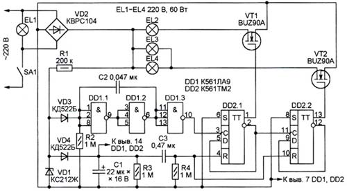
The first time after a long ( more than 15 ) off the contacts switch SA 1 will include only the EL lamp 1, which mains voltage is applied directly. Pulsating voltage supplied from the diode bridge VD 2 through resistor R 1 is limited by the Zener diode VD 1 to Almost 12 V. this value through the diode VD 4 will be charged the capacitor C 1. Take off the voltage nourishes chip DD 1 and DD 2. The pulse generated by the differentiating circuit R 4 C 3 in the process of increase of the supply voltage, sets triggers circuit DD 1 in original condition with low logic levels at the outputs 1 and 13. As a result, field-effect transistors VT 1 and VT 2 are closed, and the lamps EL 2 - EL 4 - off . Since the capacitor 2 does not have time to significantly recharge in the pauses between pulses at 100 Hz delivered through the diode VD 3, the level at the counting input of the trigger DD 2.1 remains low. The condition triggers, and lamps EL 2 - EL 4 is not changed.
If to disconnect the contacts of the switch SA 1, the voltage across the Zener diode VD 1 will fall to zero, but on the capacitor C 1 it some time will remain almost unchanged, continuing to feed the chip. After 30 MS required for charging the capacitor With 2-level switching element DD 1.1, the condition of all elements of the chain DD 1.1 - DD 1.3 would be reversed. Increasing the level difference at the input triggers DD 2.1 will be put in the high level at the output 1.
Upon subsequent closure of switch SA 1 voltage noticeably failed to discharge the capacitor C 1 will increase slightly and the momentum of the initial installation of the triggers will not be generated. As a consequence, in addition to the EL lamp 1, light comes on and the EL lamp 2, a power supply circuit which can be closed by an open transistor VT 1.
Another short-time opening of the switch will return the trigger DD 2.1 to its former state, but the high level will be installed at the outlet 13 of the trigger DD 2.2. Will include three lamps - EL 1, EL 3 and EL 4. And finally, the third flick of a switch will include all four lamps. Then the cycle repeats.
Necessary to manage the chandelier length of the opening contacts of the switch may be in the range of from approximately 30 MS to 15 s, which is very simple to withstand manually. If the device remains off longer sufficient for the full discharge of the capacitor C 1 is the current consumed by the circuits and the current through the resistor R 3, enabling the triggers go into the original state and will light only one bulb chandeliers.
Length off the chandelier needed to return to its original state, you can decrease or increase, respectively, by changing the value of the resistor R 3. Limit its increase depends on the current consumed by the chip, and the leakage current of the capacitor 1.
The device may be applied to the resistors and capacitors of any type. The component values of the circuits R 2 C 2 R 3 C 1 and R 4 C 3 can be reduced or increased in several times, but so that the product of the resistance of the resistor to the capacitance of the corresponding capacitor ( time constant ) remained unchanged.
Field-effect transistors with insulated gate VT 1, VT 2, and VD diode bridge 2 shall withstand a voltage of At least 400 and occurs when you turn on incandescent inrush current several times higher than its nominal value. Indicated in the diagram, the bridge LW PC 104 and transistors BUZ 90 A allow you to control the chandelier with lamps of a power not exceeding 60 watts. Instead of diodes KD 522 B other suitable low-power silicon.
Chip TO 561 LA 9 and 561 TM 2 can be replaced by their functional equivalents from other integrated circuit of CMOS structure, both domestic and imported. When using chip series To 176, is designed for a supply voltage of 9 V, the Zener COP 212 W should be replaced by D 814 B or another with close to 9 In voltage stabilization. It is acceptable to the replacement of other chips that contain a sufficient number of logic elements such as inverters and audit triggers. But the scheme will, of course, be changed accordingly.
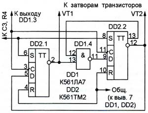
The figure below shows a diagram of the trigger of the control unit for chandelier with three lamps ( lamp missing EL 4). Thanks to the DD element 1.4 excluded the state in which the EL lamp 3 is turned on and the EL lamp 2 does not. Place of chip elements To 561 LA 9 ( DD 1.1 - DD 1.3, see Fig. 1) took three element chips TO 561 LA 7.
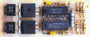
The appearance of this variant of the control device shown below. These two diode bridge DB 156 are connected in parallel to increase the allowable pulse current. Drawing of the PCB is provided as a significant part of the compounds are hinged wires.
Before installing the chandelier made the device should be checked for serviceability. It is recommended to do it at reduced to a safe value, the voltage supplied through the transformer. Lamp 220V, you can temporarily replace the low voltage power of a few watts or to use instead of the resistors of the proper resistance and power. At the time of establishing parallel to the resistor R1 temporarily connect another, impedance 1 kOhm, just remember to remove it before applying the voltage of 220 V at the end of the test.
Author: S. Gibin, Moscow; Published: www.cxem.net