The problem of the durability of incandescent lamps, which sometimes blows at the moment of their inclusion in the network remains relevant. Some solutions described in the proposed materials.
...relay and SCR
It is known that the resistance of the filament lighting the lamp in the cold state is much less than the hot filament resistance. For this reason, include only the lamp, the current through the filament significantly exceeds the rated and it sometimes burns out. This happens most often when turning on the lamp coincides with the maximum of the half-wave of the mains voltage.
One of the options to extend the "life" of a lamp is to be connected in series with it semiconductor diode. Then the probability of coincidence of the moment of switching with the maximum of the half-wave [1], because the lamp will now to flow current in one direction only, say, in the positive or negative half-cycles.
Since this diet decreases the light output of the lamps, often use the machines, which after preheating the filaments fed to the lamp full voltage. "Inrush" current is in this case less dangerous compared with the alternative of applying a voltage to the cold filament. So carry out two-stage inclusion of the incandescent lamp, can significantly extend its service life.
In 1990, the author was requested device [2], working on this principle. However, it was collected on scarce while the transistor KTA used in automotive ignition systems.
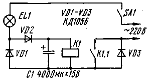
Such a device is quite possible to do more on the available details, in particular on the relay (Fig. 1) instead of the transistor. It also represents a dipole, and therefore can be easily integrated into the existing wiring. But unlike the prototype provides a smooth limit of the current flowing through the lamp at the time of inclusion in the network, and speed: first through the filament runs only one half of the half waves of the alternating current, and after a while both.

Fig. 1
Relay K1 is triggered by current flowing through the power switch SA1, lighting the lamp EL1, the relay coil, diode VD3 (or closes a group of contacts K1.1).
Device works well. After closing the contacts SA1 through the lamp pass only the positive half of the current. In this case, the diode VD1 is closed, since the contacts K1.1 is still open. The capacitor C1 is gradually charged through the lamp and the diode VD2, and as soon as the voltage across it reaches a certain value will trigger relay K1, the contacts K1.1 which sauntered diode VD3. The result is burning first "dimly" lamp EL1 will flash a bright light. Output delay for this mode depends mainly on the capacitance of the capacitor and the resistance of the relay coil.
Since the relay coil is in series with the lamp, its resistance should be agreed with the lamp power. If you use a common automotive relay with a coil resistance of 85 Ohms, the lamp may be rated from 40 to 100 watts. Then with a lamp of 40 watts on the relay coil will drop the voltage of about 7 V, 60 W 10 V, 100 W - V. 16
When any of these voltages is small automotive relay 111.3747, 112.3747, 113.3747, 113.3747-10, 114.3747-10, 114.3747-11, 116.3747-10, 116.3747-11, 117.3747-10, 117.3747-11, designed for a rated voltage of 12V, will surely be triggered. The relay outputs are labeled: 85 and 86 are the coil, 30 and 87 - normally open contacts.
From relays of General application can be recommended for lamps with a capacity of 40 to 100 watts RAS passport RS4.524.304, RS4.524.302, RS4.524.308 (the last two only for lamps 40 and 60 watts) and RAS passport RS4.524.202, RS4.524.203. With capacitor C1 capacitance to 4000 µf delay time of the relay reaches 1, that provides the desired preheating of the filament lamp. Moreover, switching the lamp on full power is almost imperceptible to the eye. Generally, experience shows that for reliable protection of the lamps is enough 100 MS [2], so sometimes recommended in the literature of the time with 2...4 [3] and even with 5...10 [4] is clearly excessive. Because heating of the lamp filament occurs with a very small time constant,
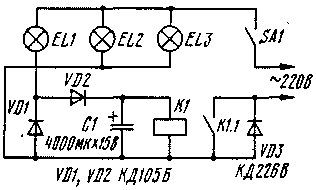
If the power switch needs to switch not one but several of the lamps (e.g., lamps chandeliers), the circuit should be split, as shown in Fig. 2. Lamp EL1 stays on still through the relay coil, a EL2 and EL3 - through diode VD3 and the contacts K1.1 relay. The additional power of the lamps is limited only by the maximum current of the diode VD3 and the allowable current through the contacts. In this embodiment, the most preferable automotive relay whose contacts can withstand current up to 30 A (though only at a voltage of 12V).

Fig. 2
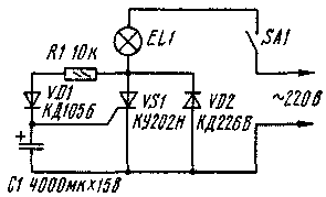
Possible and contactless method of switching circuit lighting bulbs, if you use the SCR (Fig. 3). After shorting the power switch SA1 first through the lamp and the diode VD2 pass only the negative half-cycle and the light is "dimly". After about a second the capacitor C1 is charged through the diode VD1 and the resistor R1 until the voltage of opening the SCR and through the lamp start to pass and the positive half of the mains voltage lamp flashes at full brightness.

Fig. 3
The lamp power (or group of lamps connected in parallel) is restricted by the limit currents of the diode VD2 and the SCR. If SCR is running without a heat sink, the power lamp (or lamps) must not exceed 200 watts.
The diodes in the considered devices can be KD105B-CDG, CDA - CDU, DB, KDV-CDD. Instead of SCR CON suitable COOL or COOL.
Literature
1. Vugman S. M., Kiseleva N. P., Litvinov B. C., Tokarev A. N. On the work of an incandescent lamp in the circuit is half-wave rectification. - Lighting engineering, 1988, No. 4, pp. 8-10.
2. Bannikov V. Protection of electrical appliances. Radio,1990, No. 12, p. 53.
3. Brewski L. Dimmer with time delay.- Radio,1989, No. 10,p. 76.
4. Nechaev I. Adjust the brightness of the lamp. Radio, 1992, No. 1, pp. 22, 23.
Author: V. Bannikov, Moscow
...on the triac
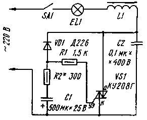
Using the property of the triac to pass both half cycle of the mains voltage, can be collected as shown in the diagram relatively simple machine that is able to limit the initial current surge through the cold filament light bulb. The machine is designed to work with lighting fixtures with a total capacity of up to 1500 watts.
The power limiter providing a two-stage lamp, works as follows. With the closure of the contacts of the power switch SA1, the current in the negative half-cycles of the voltage flows through the lamp EL1, the inductor L1, diode VD1, a current limiting resistor R1 and the circuit control electrode of the triac. The triac is opened for these half-cycles, and the light is "dimly".
At the same time during these half-cycles through the resistor R2 to charge the capacitor C1. After 1...2, when the filament lamp is already warmed up, the capacitor C1 is charged up to this voltage at which the triac will open and in the positive half-cycles of the mains voltage - the brightness of the lamp will increase to normal.

To reduce interference in the network arising from the operation of the triac, there is a filter of inductor L1 and capacitor C2. If the noise is not a limitation, these parts of the filter set is optional.
Triac COG in the device it will replace CUV. Resistors - MLT-0,5, capacitor C1 - C50-16, C2 - K73-16, K73-17 or another for a rated voltage of at least 400 V. In place of the diode VD1, except when indicated in the diagram, you can install DA, CDB, CDU or another with a reverse voltage of 300 V. the Inductor is wound on a segment of the rod with diameter of 8 or 10 mm and a length of 60...70 mm ferrite NN or with permeability of 400, its winding (turn to turn in one row) contains 50...60 turns of wire sew-2 to 1.0.
Establishing device is reduced to the selection of the resistor R2, depending on the threshold of opening applied to the triac. To do this, connect to the device load, which will work automatic, and instead of the resistor R2 temporarily fluster variable resistor a resistance greater than 300 Ohms. Dragging the slider of the resistor and feeding voltage switch SA1, choose the resistor value at which the lamp lights EL1 full intensity after 1...2 after power on. Then R2 in place permanent solder a resistor of this (or maybe close) resistance.
Because the machine is made in the form of a dipole, its parts can be placed in the housing of the lamp or chandelier without running additional wires. If the total power of the lamps chandeliers exceeds 300 W, the triac is mounted on the radiator with the cooling surface of at least 100 cm2 .
Author: A. Novikov, Perm; Publication: N. Bolshakov, rf.atnn.ru


