


")

Device "Pulse"
To convert the data of the pulse into an electrical signal is used photoelectric sensor. The sensor consists of a light bulb from a flashlight L (see Fig. and photoresistor FS-K1, between which is placed a finger investigated patient.
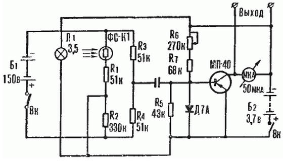
With each receipt of a portion of the blood in the finger volume increases, that reduces the amount of light passing through the finger and illuminating the photosensitive surface of the photoresistor. In this case the resistance of the photoresistor increases slightly. The photoresistor is connected to the circuit bridge. The bridge is powered from battery B1 at 150 V. From the output of the bridge peremennoe the voltage corresponding to changes in Travancore finger through the condenser C1 is fed to transistor amplifier. In the collector circuit of the transistor included microammeter MA, the needle of which varies in time with the pulse. Microammeter serves to control the correct installation of the sensor on the finger of a person. Sensor strengthen to the first phalanx of the finger against the nail so that the nail has been facing the light, and your finger is to foetoprotein.
Installing the sensor, change the degree of pressure to the finger, which is governed by screw. There is a pressure sensor on the finger, at which the signal the sensor receives the greatest. In this case, the needle of the microammeter will greatly fluctuate.
The magnitude of the sensor signal greatly affects the cardiovascular system researched and temperature of the finger. For stable operation of the device is very important, the hand was warm. If the hand is cold, it should grind to improve circulation.
Before work a variable resistor K6, the arrow of the microammeter set close to division 40 of the bookcases of the microammeter. As for the darkening of the photoresistor between him and the light, you must place a piece of paper.
For data transmission of the pulse on the distance to the output terminals of the device connects wired line, which leads to the researcher. To the line connects microammeter or a recording device. When you connect the microammeter the pulse is counted by the number of fluctuations in the direction microammeter per minute. In the case of the use of the recording device, in addition to heart rate, you can determine arrhythmia heartbeat (if it exists).
Device "Take a breath"
Device "Breath" (see picture), designed by us, is intended for transfer to a distance by wire daily on the frequency of human breathing.
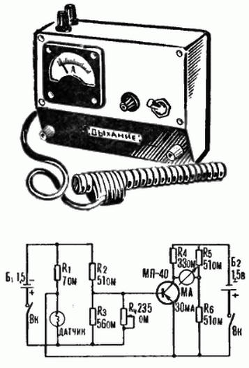
To convert the frequency of breathing into an electrical signal is applied wire the sensor, which is the usual lamp flashlight, which removed the glass cylinder. The lamp is placed in a tube with a length of 150 mm. Thread the lamp is in a heated condition due to passing through it an electrical current. The tube is placed near the nose of the person so that the flow exhaled air passed through it. When you inhale and exhale thanks to the movement air filament lamp cools down a bit, which reduces its resistance.
Wire sensor is connected to the circuit of the bridge. The bridge formed by resistors R1, R2, R3 and wire the sensor. The bridge is powered by a galvanic cell B1. From the output of the bridge weak electric signal is fed to transistor amplifier. The output amplifier included milliammeter, the arrow which oscillates in rhythm with your breathing.
Data on the frequency of respiration on the distance to the milliammeter using the output terminals connects conductive line, at the end of which (at researcher) connects the meter or recording device. A recording device will provide data not only on the frequency of breathing, but also on the duration of inhalation and exhalation and change the rhythm of breathing.
The initial position of the needle of the milliammeter device variable is set resistor R4. The resistor R1 in the manufactured device consists of eight parallel connected resistors aircraft type is 0.5 to 56 ohms. You can apply and homemade wire resistor. To increase the stability of the filament lamp must be soldered to its conclusions. Otherwise in the process as a result of oxidation of the thread and the conclusions of the lamp will increase the resistance contact between them that can disrupt the normal operation of the sensor.
The device is designed and manufactured in the laboratory of automation and technical Cybernetics CUT SB as USSR.
Author: A. Terek