


")

Treatment electromagnetic waves are widely used in medicine. Here will be considered device for the treatment of IR and laser radiation. Infrared radiation penetrates in the body's tissues to a depth of 3-5 cm Depth of penetration of laser radiation depends on the power of the applied laser. Usually used lasers from 2 to 50 mW. In this case, used a laser pointer with power up to 1 mW. The pointer without any need of alteration can be used for stimulation of biologically active points in the mode of sedation. And instead of the infrared radiation device in rough approximation to use the remote control of the TV. However there are time-tested pulse parameters that is optimal for human exposure. The frequency of these pulses must be within 50-100 Hz, modulation from 0.5 to 3 seconds.
Scheme the device is tested on a laser from a laser pointer and two IR LEDs.
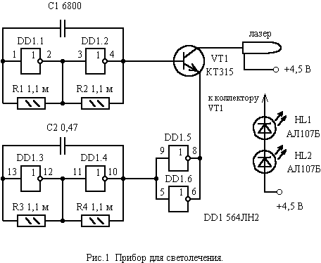
The scheme is a (see Fig. 1) two multivibrator summarizing their the pulses on the transistor. The multivibrator on the elements DD1.1, DD1.2 produces pulses a frequency of 66 Hz. And the multivibrator on the elements DD1.3, DD1.4 produces pulses with a period of 1.2 C. the VT1 Transistor operates load only half period (0.6 s) of the second generator. One logic element outputs a in the logical zero mode current 5 mA. Therefore, the outputs of logic elements DD1.5, DD1.6 are connected together to increase the output current to 10 mA. This is valid for items that are on a single chip.
Load transistor can serve as a laser from a laser pointer, and two infrared led ALB. The device is powered from the three elements of the A13, which are used to power the laser pointer.
Printed the fee for the device in the housing of the laser pointer shown in Fig. 2.
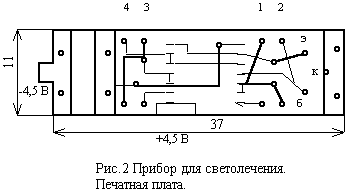
Laser pointer disassembled and carefully vapiwala button. The printed circuit Board shortened sidecutters on the resistor. Manufactured Board is soldered to the strip foil. The button is inserted into the new Board. The body of the pointer is extended plastic tube. Well suited from plastic bottles. The supply plus need to spend the wire to the chip and the laser housing. The capacitors on the Board are set on the reverse side and are soldered to the pins of the resistors. If there is no need to make a portable device, the chip LN can be replaced by K561LN2. To make the printed circuit Board in this case will not be easy.
Publication: www.cxem.net