To the transmitting and receiving devices in the UHF range very often used a master oscillator with a quartz resonator and the subsequent frequency multiplication. It complicates the design and adjustment due to the presence of harmonic components, therefore, the transmitter can "pollute" the air.
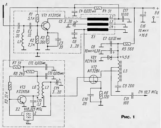
Good results have been obtained by using local oscillators, where stabilizing element resonators are used on surface acoustic wave (saw). The scheme is one such approach is shown in Fig. 1.

The first cascade transistor VT1 - low-noise amplifier (LNA) with a resonant load Z1 - has a bandwidth of 6...10 MHz (-3 dB). Filter upper frequencies C1L1C2 at the input stage serves to cutoff frequency meter range. Cascade transistor VT3 is a heterodyne, where stabilizing the resonator element is used surfactants (Z2) on 418,325 MHz. Contour with strong communication L6C15L7C14 serves to provide the necessary rotate the phase of oscillation in the feedback loop.
The mixer is made on dfugstore field VT3 transistor with a barrier of a Schottky APA. Its input capacitance of the second gate is negligible, and it allowed to connect directly to the load circuit of the local oscillator, eliminating when this buffer amp and without compromising the quality factor of the circuit, which is very important for produce a stable frequency and amplitude of vibration. Load mixing cascade - resonant circuit L5C9, tuned to a frequency of the if of 10.7 MHz. The measured noise figure of the Converter - 2.4 GHz...3 dB. Temperature instability is 2.6·10-6.
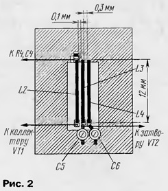
The mounting device is made using the chip-elements (mainly foreign production) on the Board size 25x42 mm. Coil L1 is 5 turns and running a wire with 0.2 mm diameter mandrel with a diameter of 4 mm. Coil L2 - L4 bandpass filter Z1 is made in the form of segments of copper wire with a diameter of 0.7 and 12 mm in length. Their relative position is shown in Fig. 2. The distance between segments may be in the range of 0.1 ...0.3 mm.

Futuremouse transformer L6L7 made of two twisted wires of 0.3 mm the "ring" from a piece of PVC tube with a diameter of 5 and a height of 7 mm, it windings have for 2 turns. Coil L5 is made on a ring with a diameter of 5 mm ferrite brand MWC and has 7 turns of wire of 0.15 mm.
The Zener diode VD1 is any voltage on the 3.8...4.2 V.
When installing the mixer must be remembered that the field-effect transistors with a barrier The Schottky sensitive to static electricity. Therefore, when working with them must be grounded soldering iron, and the transistor during soldering to close between all the findings.
Note that the cascade LNA with a resonant load can be excited due to the presence of parasitic capacitance collector-base VT1, so you should carefully to watch that. Self-excitation can easily be fixed detuning circuits filter Z1, for example, putting a ferrite ring (MVC) for the output of a collector of VT1. The gain of the stage does not make sense to do more than 7...10 dB.
If lo generation does not occur or it is unstable, you should to reduce the height of the tube to 5 mm and a diameter up to 3 mm. the parameters elements of the local oscillator to remain unchanged. More "thin" setting is produced by changing the distance between the coils.
The device was successfully applied in the receiver burglar alarm, operating at a frequency of 407,625 MHz. When the transmitter power is only 10 mW confident communication was carried out at a distance of 600...700 m (directional antenna).
It should be noted that the filter surfactants may be "nagahora" frequency response and generation to occur on one of the "humps". As a result external influences (changes in temperature, supply voltage, etc.) excluded "switch" generation frequency within the bandwidth of the filter.
Author: Y. Vladykin, Moscow


