


")

The quartz filter is, as you know, "half of a good transceiver". In the proposed article provides practical design dvenadcatiletnego quartz filter primary selection for high quality transceiver and consoles to your computer, allowing you to customize this and any other narrowband filters.
In Amateur designs in recent times as the main filter selection use quartz vosmikanalnymi the ladder-type filters, performed on identical resonators. These filters are relatively simple to manufacture and do not require high material costs. For their calculation and modeling written computer program. The filter characteristics are quite meet the requirements for good reception and signal transmission. However, when all the benefits of these filters has a significant disadvantage - some the asymmetry of the frequency response (flat low-frequency slope) and correspondingly low Squareness ratio.
Congestion of the radio broadcast defines strict requirements to selectivity modern transceiver adjacent channel, so the filter main selection must ensure that the attenuation outside the passband is not worse 100 dB when the Squareness ratio of 1.5-1.8 (-6 levels/-90 dB). Naturally, the loss and ripple in the passband of the filter should be minimal.
Guided by the recommendations set forth in [1], the basis was selected desaturating ladder filter with Chebyshev characteristic when the uneven frequency response of 0.28 dB. To increase the steepness of slopes parallel to the input and the output filter introduces additional circuit consisting of a series included quartz resonators and capacitors. Calculations of the parameters of the resonators and filter was carried out according to the method described in [2]. For bandwidth filter to 2.65 kHz were obtained, the initial values C1,2 = 82,2 pF, Lкв= 0,0185 GN, RH = 224 Ohms. The filter circuit and the calculated values of the values of the capacitors shown in Fig. 1.
In the design used quartz crystals for TV PAL decoders the frequency 8,867 MHz, produced by the all Russian Institute (g Aleksandrov, Vladimir region). Its role in the selection played a repeatable parameters of crystals, their small size and low cost. Selection frequency quartz resonators for ZQ2 - ZQ11 was carried out with an accuracy of ±50 Hz. The measurements were carried out using homemade oscillator and industrial frequency. Resonators ZQ1 and ZQ12 for parallel circuits are selected from other batches of crystals with frequencies respectively below and above the filter frequency is approximately 1 kHz.
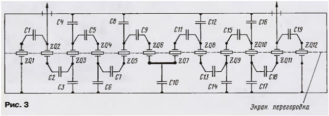
The filter is assembled on a printed circuit Board from a two-sided foil fiberglass thickness of 1 mm (Fig. 2).

The top layer of metallization is used as a General wire. The openings from the side of the unit resonators razzenkovannoe. The bodies of all quartz resonators are connected to the common wire by soldering. Before installing parts printed circuit Board filter sealed in box tinplate with two removable lids. Also by printed conductors soldered screen-partition extending between the findings of the resonators in the Central axial the line card. In Fig. 3 shows a wiring diagram of the filter. All capacitors in the filter - KD and km.
After the filter has been made, the question arose: which way home conditions to measure its frequency response at maximum resolution? Was involved home the computer with the subsequent check of the measurement results by constructing the frequency response of the filter points with the use of selective microvoltmeter.
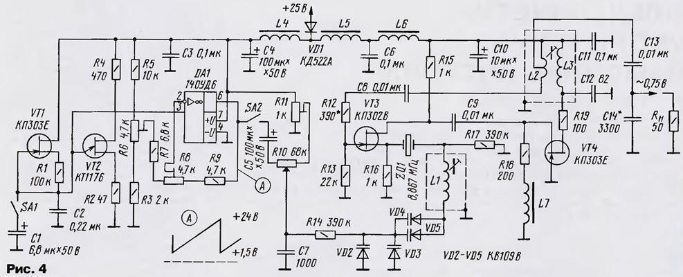
To view the frequency response of the filter at the level of -100 dB, the generator must have side level of noise below a specified value, and the detector good linearity when the maximum dynamic range of 90… 100 dB. For this reason the noise generator was replaced with a traditional sweep generator (Fig. 4).
(click to enlarge)
Based on the crystal oscillator circuit [4], whose relative power spectral density of the noise is equal to 165 dB/Hz. This means that a noise power generator when the detuning of 10 kHz in the band of 3 kHz less power the fundamental oscillation of the generator 135 dB!
The scheme of the original is a little modified. So instead of bipolar transistors applied field, and consistently with quartz resonator ZQ1 included contour, consisting of inductors L1 and varactors VD2 - VD5. The oscillator frequency reconstructed relative frequency of quartz in the range of 5 kHz, which is quite enough to measure the frequency response of the notch filter. Quartz resonator in the generator is similar to a filter In the generator mode, sweep control voltage of the varactors VD2 - VD5 served with sawtooth generator voltage, performed on single-transition VT2 transistor with a current generator on VT1. For manual adjustment of the oscillator frequency applied multi-turn the resistor R11. DA1 chip operates as a voltage amplifier.
From the originally conceived sinusoidal control voltage had to unsubscribe due to the uneven speed of the aisle sweep different portions of the frequency response of the filter, and for maximum resolution of the oscillator frequency is reduced to 0.3 Hz.
The switch SA1 is selected the oscillator frequency of "saw" - 10 or 0.3 Hz. The deviation of the frequency sweep is set trimming resistor R10.
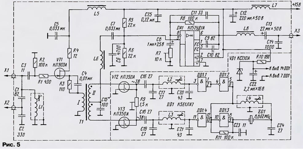
Schematic diagram of the detector unit shown in Fig. 5. The signal output from quartz filter is input to x2, if the circuit is used in L1C1C2 the load filter. If measurements are taken on the filters, loaded at the resistance of this circuit is not needed. Then the signal from the load resistor is input to X1, and on the PCB of the detector conductor is removed, connecting the input X1 of the circuit.
(click to enlarge)
Source follower with a dynamic range more than 90 dB at powerful field transistor VT1 agree on the load resistance and input filter resistance of the mixer. The detector is made according to the scheme of passive balanced mixer on field-effect transistors VT2, VT3 and has more dynamic range 93 dB. At the United gates of the transistors via the N-contours C17L2C20 and C19L3C21 do anti-phase sinusoidal voltage with level 3 4…V (RMS.) from the reference oscillator. In the reference generator of the detector is made on the chip DD1, installed quartz resonator with a frequency of 8,862 MHz.
Formed at the output of the mixer, the low-frequency signal is amplified in about 20 times the amplifier on a chip of DA1. Since sound cards personal computers have a relatively low impedance input, the detector is fitted with a powerful OS COD. The frequency response of the amplifier is adjusted so that the lower frequency of 1 kHz and above frequency 20 kHz was observed a decline in gain is approximately 6 dB per octave.
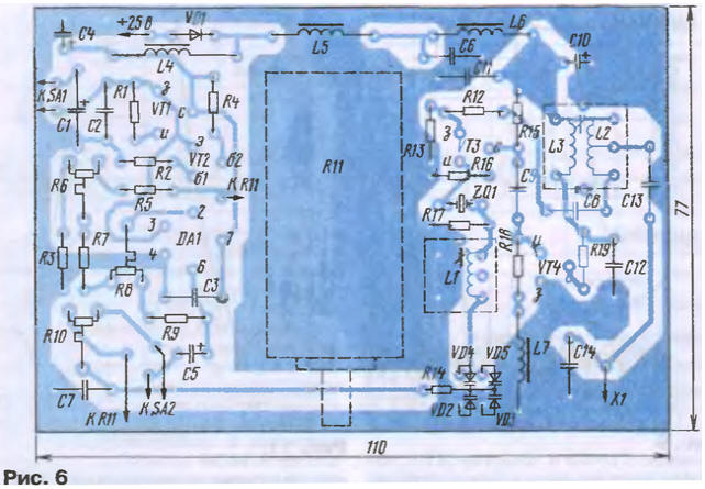
The sweep generator is mounted on the PCB of bilateral foil fiberglass (Fig. 6). The top layer serves as a common card wire hole findings of the details, not having contact with him, razzenkovannoe. Board sealed in a box with a height of 40 mm with two removable covers. Box made of tinplate.

Inductors L1, L2, L3 are wound on standard frame with a diameter of 6.5 mm trimmers carbonyl iron and placed in the screens. L1 contains 40 turns of wire sew-2 0,21, L3 and L2, respectively, 27 and 2+4-loop wire PELSHO-0,31. The coil L2 is wound on top of the L3 closer to the "cold" end. All chokes standard - DM 0,1 68 µh. Fixed resistors MLT, customized R6, R8 and R10 type SDR-38. Multi-turn resistor - PPML. Permanent capacitors - km, KLS, CT, oxide - K50-35, K53-1.
The establishment of the sweep start with setting the maximum signal at the output of the generator the sawtooth voltage. Controlling the oscilloscope, the signal at pin 6 chip DA1, trimmer resistors R8 (gain) and R6 (offset) set the amplitude and waveform of the signal shown in the plot at the point A.
The selection of resistor R12 achieve sustainable generation without entering the mode limitations of the signal. Selecting the capacitance of the capacitor C14 and adjusting the circuit L2L3, adjust the output oscillatory system in resonance, which guarantees good load capacity of the generator. The podstroechnik coil L1 set the limits of adjustment of the generator within 8,8586-8,8686 MHz, with the reserve covers band frequency response test of the quartz filter. To ensure maximum adjustment sweep (not less than 10 kHz) around the connection points L1, VD4, VD5 upper foil layer removed. No load output sinusoidal voltage the generator is equal to 1 V (RMS).
The detector unit is formed on the printed circuit Board from the foil dvustoronne fiberglass (Fig. 7). The upper foil layer is used as a General wire. The holes for the conclusions of parts not in contact with the common wire, senkut. Board sealed in a tin box with a height of 35 mm with removable lids. The quality of workmanship consoles depends on its resolution.
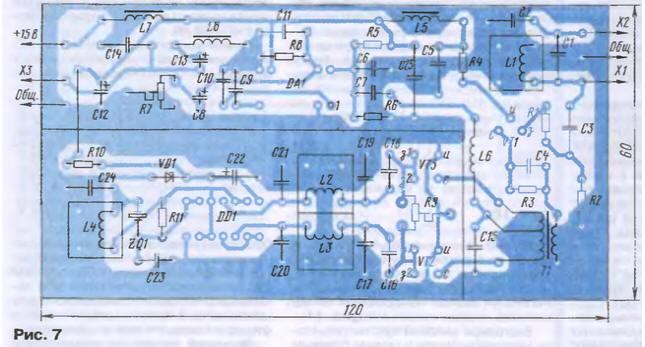
Coils L1-L4 contain 32 turns of wire sew-0,21 wound coil to a coil on frames with a diameter of 6 mm. the Trimmers in coils from armored core SB-12A. All chokes DM type-0,1. The inductance L5 - 16 µh, L6, L8 - 68 µh, L7 - 40 mH. Transformer T1 is wound on a ferrite ring cores NN size K10h6h3 mm and contains a primary winding 7 turns, secondary - 2x13 turns of wire sew-0,31.
All trimmer resistors - GPA-38.
During the presetting unit high frequency oscilloscope control sinusoidal signal on the gates of transistors VT2, VT3 and, if necessary, adjust the coils L2, L3. The podstroechnik coil L4 frequency reference generator will be moved below the bandwidth filter at 5 kHz. It is done to ensure that the working area of the spectrum analyzer less we observed various interference that reduces the resolution of the device.
The sweep generator is connected to a quartz filter through a matching resonant circuit with the capacitive divider (Fig. 8).
In the process of configuring it will allow you to get small attenuation and flatness in the passband filter. A second matching of the resonant circuit, as already mentioned, is in the detector unit. After collecting the measuring circuit and connecting the output of the console (connector X3) on MIC or line input of a sound card of a personal computer, run the program spectrum analyzer. There are several such programs. The author used a program SpectraLab v.4.32.16, posted address: http://cityradio.narod.ru/utilJties.html. The program is convenient in use and has great features.
Now, run the program "SpektroLab" and, adjusting the frequency sweep (mode manual control) and the reference oscillator in the detector box, set peak spectrogram sweep on the mark 5 kHz. Further, balancing the detector mixer consoles, the peak of the second harmonic is reduced to the noise level. After that turn on sweep mode and the monitor appears a long-awaited response of the test filter. First turn on the swing frequency of 10 Hz, and adjusting with R11 the center frequency, and then swing R10 (Fig. 4) installed acceptable "image" frequency response of the filter in real time. During measurements, adjusting the matching contours, achieve a minimum of irregularity in the band transmission. Further, to achieve maximum resolution the device includes a swing frequency of 0.3 Hz and install the program the maximum possible number of points of the Fourier transform (FFT, the author 4096..8192) and the minimum value of the parameter averaging (Averaging, the author 1). Since the characteristic is drawn in several passes sweep, mode storage peak voltmeter (Hold). In the end, on the monitor, get response the investigated filter. Using the mouse cursor to the desired digital the values of obtained amplitude-frequency characteristic at the desired levels. Thus it is necessary not to forget to measure the frequency of the reference oscillator in the detector box, to get the true values of the frequency points of the frequency response.
Estimating the original image, adjust the frequency of the serial resonance ZQ1n ZQ12 respectively on lower and upper slopes of the frequency response of the filter, achieving maximum direct-moralnosti at the level of -90 dB. In conclusion, using printer receive a full document on the manufactured filter. As of example in Fig. 9 shows the spectrogram of the frequency response of this filter. There are also the spectrogram of the signal sweep. The apparent irregularity of the left slope of the frequency response at the level of -3…-5 dB is eliminated by rearrangement quartz resonators ZQ2-ZQ11.
Finally, we obtain the following filter characteristics: bandwidth level -6 dB - 2,586 kHz, frequency response in the passband is less than 2 dB, Squareness ratio by level -6/-60 dB - 1,41; levels -6/-80 dB - 1.59 and the levels -6/-90 dB - 1,67; the attenuation in the band is less than 3 dB, and for band - more than 90 dB.
The author decided to check the results obtained and measured frequency response of the quartz filter points. For measurements required selective microvoltmeter with good attenuator, which served as a microvoltmeter type HMV-4 (Poland) with a nominal a sensitivity of 0.5 µv (at the same time, well fixing the signal level 0.05 mV) and the attenuator 100 dB.
For this measurement was collected diagram in Fig. 10. Matching circuits at the input and output of the filter is carefully screened. Connecting a shielded wire used is of good quality. Also carefully executed "ground" circuit.
Gradually changing the frequency sweep resistor R11 and switching to 10 dB attenuator, take readings microvoltmeter, passing across the frequency response of the filter. Using data measurements on the same scale, we build a graph of the frequency response (Fig. 11).
Due to the high sensitivity of the microvoltmeter and the postern noise sweep well recorded signals at the level of -120 dB, which is clearly reflected on the chart.
The measurement results were as follows: bandwidth-6dB - 2,64 kHz; frequency response - less than 2 dB; Squareness ratio by levels -6/-60 dB is $ 1,386; levels -6/-80 dB was 1.56; the levels -6/-90 dB - 1,682; levels -6/-100 dB - 1,864; the attenuation in the band is less than 3 dB, for band - more than 100 dB.
Some differences of measurement results from the computer version are explained the presence of accumulated error digital-to-analog conversion when you change the analyzed signal in a large dynamic range.
It should be noted that the frequency response graphs of the quartz filter is obtained by a minimum amount of setup work and a more careful selection of components, the filter characteristics can be improved.
The proposed scheme of the generator can be successfully used for measurements single-signal selectivity, and also to measure dynamic range transceivers 110…120 dB.
This device can be successfully used to assess quality indicators of tract FC transceivers, work ARU and detectors. Signaled the sweep generator to the detector, the output of the console to PC get the low-frequency signal generator sweep frequency, with which you can easily and quickly configure any filter and the cascade low cut path of the transceiver.
It is interesting to use the proposed detector prefix in the composition panoramic indicator of the transceiver. This should be connected to the output of the first mixer crystal filter with a bandwidth of 8…10 kHz. Next, the resulting the signal to enhance signal to the input of the detector. In this case, it is possible to observe signals their correspondents with levels from 5 to 9 points with a good resolution ability.
Literature
Author: G. Bragin (RZ4HK)