The audio frequency amplifier, whose scheme is shown in Fig. 1, is designed for simple cohesive devices - superheterodyne and sinks direct conversion.
The gain of this USC about 1000 (60 dB). Stripe bandwidth from 250 to 2700 Hz (- 6 dB). For receiving Telegraph signals can narrow down to 300 Hz at an average frequency of about 900 Hz.
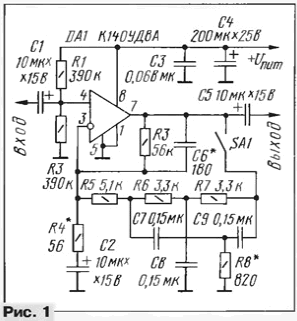
USC realized by operational amplifier DA1, the mode of operation in which the permanent current sets the divider resistors R1, R2. The audio signal is supplied to the non-inverting input of op-amp and its inverting input from the output of op-amp the signal feedback. It passes through an RC circuit, which determine the coefficient the gain of the device and its amplitude-frequency characteristic (AFC).
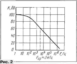
When the contacts of the switch SA1 turns off, the frequency response of the amplifier form the resistors R3, R4 and capacitors C2, C6. At medium frequencies (1 ...2 kHz) gain It is determined only by the resistors R3 and R4. Since the signal is fed to the non-inverting input, then K=1+R3/R4. When shown in Fig. 1 the values of these resistor the gain will be about 1000. Note that 1000 - the maximum allowable gain USC when using operating amplifier COD and some other operational amplifiers with internal correction. This is illustrated in Fig. 2, which shows the frequency response of the actual OS. It is seen that for large values of the gain even without considering the impact add-on elements, the bandwidth is already less than the required 3 kHz.
The frequency response of the amplifier at low frequencies primarily forms a chain R4C2. On frequency F=1/2pR4C2 the gain is reduced by 3 dB relative to the mid frequencies. It is easy to verify that under these scheme, the values of this will occur at a frequency of about 280 Hz.
At high frequencies the frequency response of the amplifier will mainly determine the frequency response of the operational amplifier DA1 (Fig. 2).
To further attenuate high frequencies by turning on in parallel with R3, the capacitor (C6), the capacity of which is selected empirically. If the OS is not effectively "filled up" the frequencies above 3 kHz, the capacity of this the capacitor shown in the diagram the value of the resistor R3 should be around 1000 pF (it is calculated according to the same formula as in the previous case). Taking into account the real frequency response of a particular instance of the OS in practice, the capacitance of this capacitor will be less. In particular, it may not be "double T - bridge", which is formed by two T - shaped chains (and R6R7C8 R8C7C9) connected in parallel.
The dependence of the transmission coefficient of the signal dual T - bridge frequency shown in Fig. 3.
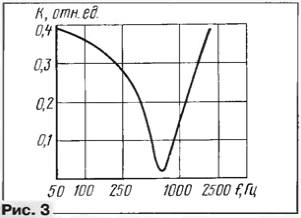
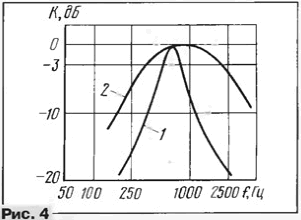
At a certain frequency (it is called the quasi-resonance frequency), the transmission coefficient of such a circuit substantially - a hundred times or more - decreases. If dual T - bridge to connect the feedback circuit of our amplifier in parallel with the resistor R3, the quasi-resonance frequency of the bridge you will have almost no influence on the transmission coefficient USC in General. At frequencies above and below this frequency negative feedback will increase (double T - bridge, as it bypasses the resistor R3), reducing the transmission coefficient of the amplifier. The result is a "resonant" frequency response (curve 1 in Fig. 4). At the same the figure given and the frequency response of the amplifier with disabled dual T - bridge (curve 2). For the 0 dB level in this figure is adopted gain USC at a frequency of 1 kHz.
The frequency of quasi-resonance double T - bridge is determined by the values of its elements. If conditions C = C7 = C8 = C9 and R = R6 = R7 = 4R8 it can be calculated according to the formula F = 0,45/RC. A small amount of quasi-resonance frequency can to change the selection of only one resistor R8.
The resistor R5 and isolating. It reduces the load of the bridge is relatively low-impedance resistor R4. If its not set, then the narrowing of the bandwidth when USC connect the dual T - bridge will be significantly smaller, i.e. the filter will be ineffective. Selecting this resistor and controlling the frequency response of the amplifier, you can set bandwidth USC when receiving Telegraph signals in according to the individual tastes of the operator.
Use in USC operational amplifier provides the advantage that the collected causing part of the design of the building does not require. If the amplifier is "not went" with the first start, check mode OU DC. The voltage at its output (pin 7) should be close to half of the voltage power source (it is set by the divider resistors R1 and R2). If it's not so, either you made an error during installation or selection of elements for construction, or just a faulty OS.
By repeating design you can use the most modern and not very modern operational amplifiers. If shelter without applied field-effect transistors (for example, COD), the resistance of resistors R1 and R2 is advisable reduce to about 100 ohms, while maintaining the condition R1 = R2. Oxide capacitors can be of any type.
The amplifier is designed for use with headphones resistance 50...100 Ohms. If there is a ham radio operator has head phones with less resistance, you have to add to this small output amplifier cascade. The supply voltage of USC - 9...12 V
A gain of 1000 is more than sufficient for superheterodyne USC receiver. For direct conversion receiver total gain tract of audio frequency must be a hundred times more, so USC, scheme which is shown in Fig. 1, in this case, the application must be supplemented by the cascade pre-amplification. Its scheme is shown in Fig. 5. It is executed on the transistor is working to reduce the level of noise in the low mode the collector current (about 0.2 mA). The gain of such a cascade is determined by the ratio of the load resistance in the collector circuit of the transistor VT1 (mostly because it is in parallel with R3 and R7) and the sum of the resistances a resistor in the emitter circuit, is not shunted by a capacitor (R4), and the resistance of the emitter junction. The latter can be estimated by a simple formula Re = 25/I. If in this formula to substitute current in milliamperes, the resistance get to Omaha. At a current of 0.2 mA emitter resistance re will be 125 Ohms. It is easy to estimate and the gain of this stage is about 80.
When calculating the gain of such a cascade is not necessary to forget about input the resistance of the subsequent cascade USC. But in our case they can be safely neglect - it is about 200 ohms (resistance of resistors connected in parallel R1 and R2 in Fig. 1). Given that the input impedance of the subsequent cascade gain pre-amplifier will decrease slightly up to 75.
The capacitor C4 limits the top bandwidth preliminary cascade value 4...5 kHz.
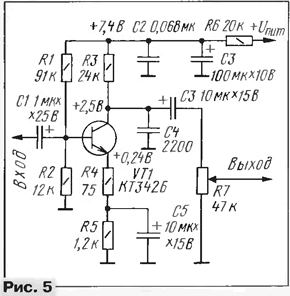
For orientation in Fig. 5 shows the modes DC voltage power supply 12 V. If it is less, it is necessary to take the filter resistor in a circuit of this stage (R6) with less resistance.


