


")

The author introduces readers to the developed computer program "BPF-PP" to calculate the parameters of the narrow-band microwave filters.
As described below, the program "BPF-PP" allows the calculation of narrow-band filters for coupled half-wave resonators. I hope that it will interest hams, developing microwave devices. The program is written in the language programming GWBASIC, can be easily transformed into any BASIC version and assumes that you have prior knowledge on technology microstrip lines (MICROSTRIP lines) and electric filters. For more information the reader will find in the technical literature, the list of which is given at the end article.
In order to rapidly obtain skills in the use of program consider a specific a calculation example. In the text content of the program displayed on the screen shown in quotes. Put that preliminary calculations or design considerations showed the need to create a second order filter with a bandwidth of from 694 to 734 MHz. Do it on the basis of bilateral foil fiberglass.
After starting the program on the screen appears:
"The type of filter marked: Butterworth (2-9 order); Chebyshev (3-9 order) - T.
Filter order (2-9)?".
To this question in our example, type the number 2. Next:
"filter type - In
the load resistance in Ohms ? 50
Border bandwidth, GHz:
Top? .734
Lower? .694
Center frequency bandwidth F0 = 0.7137186 GHz"
On request
"Foil thickness t, mm?
The thickness of the substrate H, mm?"
you must enter the dimensions in millimeters of the material used. For example, the thickness of foil t = 0.05 mm, glass fibre laminate and the substrate is H = 1.5 mm.
On request "Dielectric permittivity E?" we introduce for our example E = 4,8.
Following this, the screen will display the results of the calculation:
"********* IS THE CALCULATION OF THE**********
the width of the associated strips W(0) =2.67 mm
the gap S(0,1 ) = 0.14 mm
a quarter - wave 52.15 mm
the width of the strips associated W(1 ) = 3.17 mm
the gap S(1,2) = 3.13 mm
a quarter - wave 51.65 mm
the width of the associated strips W(2) = 2.67 mm
the gap S(2,3) = 0.14 mm
a quarter - wave 52.15 mm"
According to the results of calculation adopted the following decision: on one side of the plate foil fiberglass have two strips of foil width W(0) and length 5,215 cm with a gap S(0,1) between them. A second pair of linked strips located on the same side of the plate to the right, right next to the first, the upper strip of the second pair should be a continuation of the bottom strip of the first pair (see figure), but its width W(1). A second strip of the second pair of length 5,165 cm placed with a gap S(1,2) under the first.
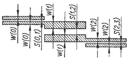
The first strip length 5,215 cm third pair with width W(2) continues the second the second pair. The second stripe third pair length 5,215 cm and a width of W(2) will be to be the first with a gap S(2,3). Foil on the second side of the plate leave solid and undamaged.
Thus, obtain the structure of the four strip lines arranged one under another with gaps S(0,1), S(1,2) S(2,3) and shifted the genuine a quarter wave. Two internal layout of the strips are half-wave resonators, but the outer two - quarter-wave elements in communication with the generator and the load. To the extreme outer ends of the strips connect the agreed load and generator or line having a characteristic impedance the same as that of the filter.
A few words about the program. Command line from the 80-th 240 th are table with filter settings - prototypes Butterworth from the second to the ninth orders and Chebyshev from the third to the ninth order with unevenness in the strip bandwidth of 0.28 dB for Amateur practice in most cases enough.
(click to enlarge)
Optionally, instead of a table of prototypes can be entered routine determining the coefficients of the prototype filters of higher orders and with other values of the variation.
It should be noted that for better convergence with practical results estimated first measure the dielectric constant fiberglass used plates. To do this, make another the plate of the same material strip line of arbitrary length, which will be serve a half-wave resonator. Near one of its ends in parallel fitted with a gap (close to real) the same line, but length 5…10 times smaller. This line will serve as the exciter resonator. For this by its one end connected to the generator, and the other load resistor impedance of 50 Ω, chosen in advance.
At the resonance frequency exactly in the middle of the resonator formed node voltage, captured by the detector head. Effective dielectric the permeability is determined from the expression  where Fрез - resonance frequency in MHz; L - the cavity length in meters. The value of the dielectric constant e of the material (in the program is administered by the letter E) obtain from the formula
where h is the thickness of the fiberglass, mm; W is the width of the strip resonator, mm.
To measure the dielectric permittivity were more reliable, should to choose the length of the cavity is quite large - 150…200 mm In this case, the presence of end capacity would make only a slight error. Through such measurements, I usually choose the width of the gap between the feed line and resonator, and the width of the line and the resonator is twice the thickness substrate. Measurement spend at a frequency of not more than 1 GHz.
Literature
Author: O. Soldatov, Tashkent, Uzbekistan