THE VALUE OF THE ELEMENTS
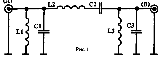
In the table below: capacitance - pF, the inductance in µh, SV - so-called citizen band 27 MHz.
Table 1
Range
C1-NW
L1-L3
C2
L2
160m
3900
1.9
390
19.2
80m
2000
0.95
200
9.5
40m
1000
0,51
100
5.1
20m
470
0.27
47
2.7
15m
330
0,17
33
1.7
ST
270
0,13
27
1.3
10m
240
0.13
24
1.3
DESIGN OF INDUCTORS
They are wound on the annular core Amidion T-80-6 enameled wire diameter not less than 1 mm for ranges from 20 to 10 meters and 0.8 mm for the rest. Winding takes about 3/4 of the surface of a torus. The circuit can be configured with two extreme turns with the gear in the middle of the range in which it will be to work.
The table shows the number of turns.
Table 2
Range
160
80
40
20
15
ST
10
L1-L3
23
16
11
8
7
6
6
L2
70
50
35
25
20
18
18
THE CHOICE OF CAPACITORS
It is best to use mica capacitors. Their data shown in the table.
THE SET OF CONTOURS
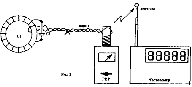
You need to include GEAR to the generation mode and place it near the frequency counter to accurately measure the frequency. Ring the core is a closed magnetic field. And for communication with GEAR used aperiodic communication line with a low resistance. Need to do is turn on the filter and coil coil coil around GEAR.Wire line connection formation between them (Fig.2).

Setup is otmuchivanie and Domitiana revolution and finally the movement and spread of the turns. At the end settings on the torus coils are fixed.
INSTALLATION OF FILTER
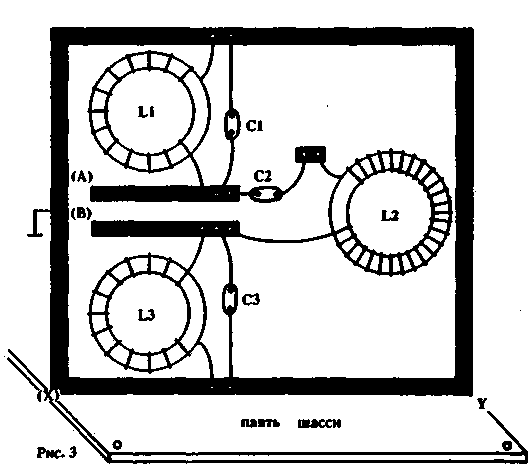
The filter is mounted on a circuit Board, a foil one side. Details are on the "clean" storn, where left only three of the contact surface and the conductor mass (Fig.3).

To eliminate spurious phenomena, these surfaces are not must be under the annular coils. Input and output filter (it is reversible) it is easy to switch using a relay that must be of good quality with contacts for a current of 1.5 A (at 100 In) and 2...3 A (At 250 V). Board mounted in design vertically.
THREE-BAND BUTTERWORTH FILTER
It looks like the letters P and contains inlet and outlet parallel resonant circuits, and between them consistent the resonant circuit. It is known that the resonant frequency Fo in parallel, the circuit is more resistance to Fo, than for other frequencies. In contrast, sequential circuit acts as shorted. Thus, L1/C1 and L3/C3 filter out frequencies that are different from Fo, a L2/C2 is for them great resistance.
Author: Pierre Willeman (F9HJ); Publication: N. Bolshakov, rf.atnn.ru


