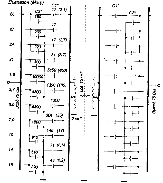
Fig.1-Band bandpass filter homemade transceiver
The bandwidth of the filter is determined by the ratio Af=l,4f/q e, where f - center frequency range; Q e - factor of the circuit. To calculate on all Amateur bands is selected to be 30.
Due to high quality of the contours in the range of 80 m, the filter bandwidth is approximately 150 kHz, so I had to split it into two sub-bands of 3.5 - 3,65 MHz and 3.65 to 3.8 MHz.

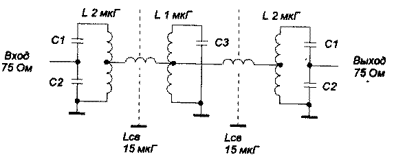
Fig.2 Single-band 3-circuit bandpass filter
The DFT contains only two primary coils, which can significantly reduce its overall dimensions and not to do shielding between the elements of the ranges. You can offer two versions of the schematic of the construct, the DFT - switchable ranges of the disk switches or small relays RES-60.
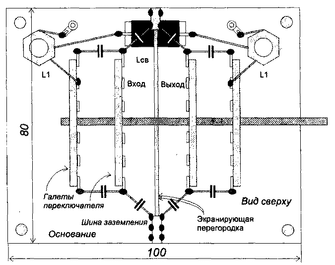
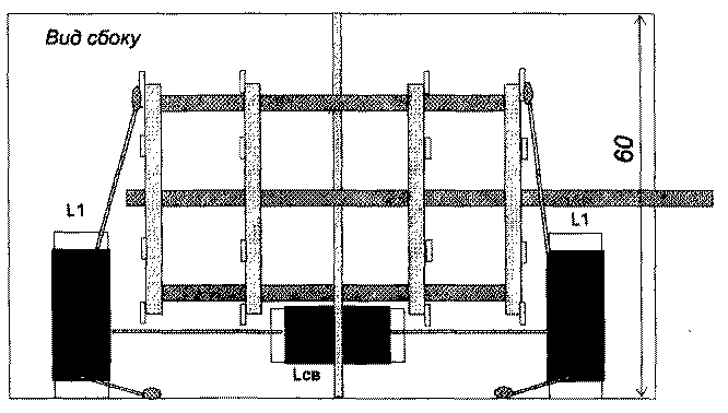
In Fig.3 shows the conceptual layout option DFT (author's version), switchable ceramic 4 disk switch. The dimensions of the filter can be somewhat reduced by using switches type GKP diameter wafers of about 30 mm. of the Coil wound on the LCB rod of insulating material with a diameter of 8 mm. Coils L1 and L2 may be wound on a suitable frame with a diameter of 12 to 20 mm.


Fig.3 Sketch of the elements of the bandpass filter
To determine the appropriate number of turns to bring the calculation formula for single-layer coils

w - number of turns; L is the coil inductance, µ; 1 - winding length, cm; D is the diameter of the coil.
The filter can be calculated at any frequency, the capacitance of the capacitors C1 and C2 are determined by the formulas

where f is the desired operating frequency.
The filter is designed for resistance Rin=Kwih=75 Ohm. The inductance coils L1 and L2 = 2 µg, LCB = 15 mcg.
In an embodiment, the DFT switches on the disk ranges from 10 to 28 MHz are conveniently placed on the petals facing up and to the sides, and the capacitors C1 to make a composite, parallel-connected ceramic trimmer capacitors CPC-M, and ceramic fixed capacitors. Trimmer capacitors for rigidity of the structure and sealed to the strips of foil fiberglass, which, in turn, is rigidly soldered between the petals of biscuits.
Capacitors C2 soldered directly between the petals of the switch and the ground bus bar is also made of a foil fiberglass, bolted to the vertical carrier screen. The values of capacitors C2 are chosen closest to the calculated values. When you configure the filter they usually are not selected. Bends in the coils L (point a) are made from the middle.
Filter setup
Filter setup is performed in the usual manner, using the GSS and RF voltmeter or that much faster and easier, with the help of meter response (XI-38, XI-48, etc.). The output of the filter is loaded with a 75 Ohm resistor. DFT is configured in two ways. On ranges equipped with trimmer capacitors, the configuration is as follows.
First, force a weakened connection between the contours L1 and L2 are parallel to the coupling coil is soldered to the capacitor, the value of which is approximately equal to 2/3 of the capacity of the compensating capacitor on each band, they are shown in parentheses in Fig.1.
Thus, each circuit, independently from each other, can be set to the middle of the range to the maximum signal GSS. Then the compensating container is cleaned and removed the AFR, which is shifted higher in frequency. Is determined by the offset frequency, again soldered the compensating capacitance and the setting procedure is repeated, but on a smaller frequency taking into account the shift amount. Vypayat the compensation capacitor, must have a final inspection of the resulting frequency response. An example of setting the filter on one of the Amateur radio bands
Custom 10-meter range at a frequency of 28.5 MHz. The desired bandwidth for 27.85... 29,15 MHz, the Central frequency of 28.5 MHz. Measured original bandwidth was 28,2 ... 29,5 MHz, i.e. smeshen above 350 kHz. Then do a reinstallation of the center frequency 28,15 MHz And VX range is in place.
At those ranges where there is no tuning capacitor, tuning easier to produce a way that is somewhat different from the previous one.
The input to the DFT of the signal of the GSS, the RF voltmeter is connected to A configurable circuit, and opposite the point a is grounded. GSS-ω is determined by the resonant frequency of the primary circuit. Switching the GSS from the DFT input to its output, is determined similarly to the resonant frequency of the secondary circuit. Choosing the value of capacitor C2, the second circuit is configured to resonant frequency of the primary circuit.
Restore the filter in the operating position, load it with 75 Ohms and remove the resulting frequency response (see example). Repeat the setup procedure with respect to the frequency shift, again, a custom circuit, selecting the capacitors C1 and C2, the corrected final response.
DFT on an impedance of 50 Ohms
If you need to do DFT with Rin=Kwih=50 Ohms, then to calculate the capacitors you can use the following formulas

3 contour DFT
For those who want to do even better the DFT, with greater steepness of slopes (note that in this case, a little will increase the attenuation in the pass band, approx. RW3AY), it is possible to offer more complicated version. The filter turns into a triple-effect system with more complex switching, Fig.2.
The inductance of the secondary coil should be twice smaller inductance extreme coils - 1 uh. On average, the circuit is sufficient to switch only one capacitor on each band. Its value can be determined by the formula
C = SS/C1+C2
Literature
Author: N. Smirnov, UA3TW, Nizhny Novgorod; Publication: N. Bolshakov, rf.atnn.ru


