In Fig.1 shows a diagram, which was used for experiments. The frequency of the quartz in the studies were 14.218 MHz. The main element that is changed in an experiment is the inductor L. in Parallel, the added resistor 22 kOhm to correct the failures of the frequency within the range. The transistor in the oscillator has a cutoff frequency of 80 MHz. As a buffer stage amplifier FET. The bias resistor RB to the first transistor equal to 100 ohms (the value of emitter current is 9 mA). Capacitors C1 and C2 150 pF. At the end of the experiment was an attempt to change the values of RB, C1 and C2. Variable capacitor - plate and has a value from multiple pF to 100 pF. The transformer T is wound on a ferrite ring with a diameter of 7 mm. the Coil is wound folded and twisted three wires PELSHO 0.2 and contains 3...4 turns. The ends of each winding are connected according to the diagram.
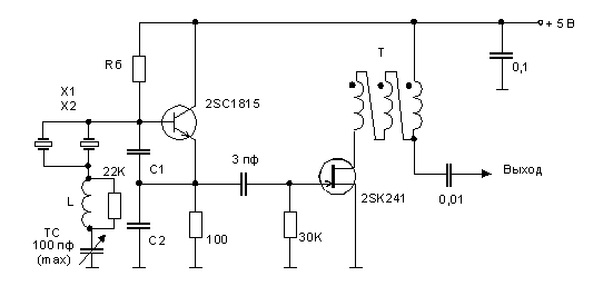
Fig.1
In Fig.2 shows the ranges of adjustment of the oscillator frequency when the capacitance change of the CU from the minimum value to 100 pF. Was used for measurement of a set of inductors L c values of 5.6, 8.2, 10, 10.39, 11 and 12 µh. To obtain the inductance 10.39 µh used two series-connected coils 10+0.39 µh, and for 11 µh - 10+1 µh. For clarity, given a curve (X1 only) the generator with one quartz. As the graph shows, for a typical oscillator frequency varies slightly with increasing inductance. At the same time for supergenerators adjustment range frequency increases rapidly up to 300 kHz (!) with L=12 mH. However, we must be careful with such a wide range of adjustment frequency due to the deterioration of stability.
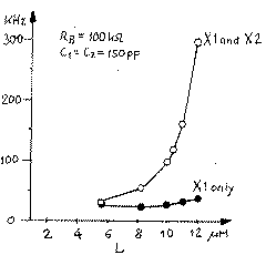
Fig.2
Fig.2 shows the drift of the frequency for three values of inductance L=10, 10.39, and 11 mH. Both quartz connected in parallel, and the capacitance of the variable capacitor TC=100 pF. The measurements were carried out after 25 minutes after pripiski appropriate circuitry. Then power on the generator and was saccules. As can be seen, acceptable stability over time was observed for L=10 µh. For values of L=10.39 and 11 µh frequency drifts in a wider range. This is most dependent on temperature coefficient of inductance. Therefore, in my practice, I stopped at the maximum value L=10 µg. Ultimately you can get a higher stability during long-time heating and if you use inductors with small temperature coefficients.
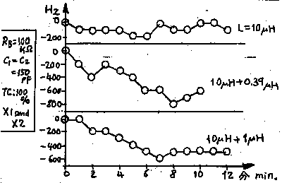
Fig.3
Now I slightly alter the capacitance C1 and C2. All other parameters are set as follows: RB=100 kω, L=10 µh, and X1, X2 in parallel. Fig.4 shows a frequency band depending on the capacitance C1 and C2. C1 and C2 were changed simultaneously. The graph shows that the frequency range get wider with increasing capacity. Measurement with C1=C2=330 pF were impossible because Vout (the output voltage at the counter) was a bit too small as shown in Fig.5. The values of C1 and C2 in 100 and 150 pF is the most acceptable in practice in this circuit.
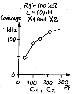
Fig.4
Finally, I changed the value of the base resistor RB. Other elements are: C1=C2=150 pF, L=10 µh, and X1, X2 in parallel. Originally, RB was set to 100 ohms in the emitter current of 9 mA. This time, RB is set at 200 ohms, the emitter current has decreased to 5.2 mA. The frequency range has not changed although the Vout(output voltage) decreased from 0.7 V to 0.3 V. Further RB was increased to 470 ohms, the emitter current has decreased to 2.4 mA. However, Vout is too low, less than 0.1 V. Therefore, the frequency was not able to measure the frequency of the signal.
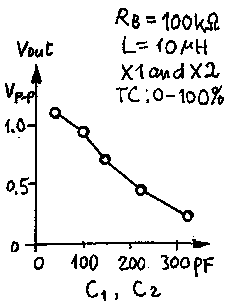
Fig.5
In conclusion, the frequency range around 100 kHz was obtained at L=10 µh, C1=C2=150 pF, X1 and X2 are connected in parallel and RB=100 kω. Stability was acceptable, but became worse with the increase of the inductance of the coil L. the Frequency range got wider because C1 and C2 have been installed in large quantities but are not dependent on the bias resistor RB.
It must be emphasized that these results are more or less specific and depend on the quartz used in this experiment. The optimum was estimated for the L, C1 and C2 may differ from the values obtained in this experiment if the quartz has other parameters, or other frequencies. Therefore, You can conduct an experiment to optimize the settings for your crystal.
Author: MINOWA, Makoto, 7N3WVM; Translation and publication: N. Bolshakov, rf.atnn.ru


