The addition of a counter made by several decade counters crystal oscillator, one multiplexer, allows to obtain a set from him up to eight fixed frequencies, for example, from 1 Hz to 10 MHz.
In the Amateur publications have been featured digital circuits of frequency using chipset series K155 (K555). We must assume that and now ham radio operators still use such appliances. Offer for the repetition of the prefix will allow this frequency to get a generator fixed frequencies.
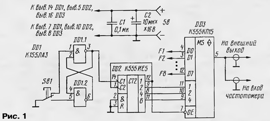
The essence of this refinement is to use the block model frequencies frequency as a source of pulse signals of fixed frequencies. As this unit consists of a pulse generator with quartz stabilization and N-stage frequency divider. Taking signals directly from the output of generator and after each stage of the divider have a set of N +1 frequencies (in this the case must satisfy the condition N + 1 < 8). If, for example, generator generates pulses with a frequency of 10 MHz, and the scheme of division consists of counters-dividers for ten, we have the grid of the following frequencies: F1= 10 MHz, F2= 1 MHz, F3 = 100 kHz F4 = 10 kHz, F5 = 1 kHz, F6 = 100 Hz, F7 = 10 Hz, F8 = 1 Hz. The proposed attachment provides transmission to its output (and at the same time to the input frequency) pulses of one of the grid frequency. Electrical diagram consoles are depicted in Fig. 1.

The device operates as follows. At power frequency on output RS-flip-flop (pin 3 DD1) established a high level. DD2 counter, connected in the circuit of the divider 16 is set to an arbitrary state, for example, in a zero. The number "zero" in the code 1-2-4-8 is transmitted from the output on DD2 the address inputs of the selector and the input of the FIRST multiplexer DD3. This combination provides signal with input D0 on direct chip DD3. So way, to the input frequency signal with the frequency F1, which is the test to check the operation frequency.
For translation of the instrument from generator mode in the counter mode you need to press button SB1 button (non-latching). At the output of the counter DD2 is set to an odd number and to the input of the FIRST multiplexer DD3 goes to a high level. He translates the output of the multiplexer in a high-impedance state (Z-state), which allows the counter to measure the frequency of the external signals. The next time you press the button SB1, the device returns to the mode generator and to the input frequency signal with the frequency F2. And so on, the ring: if the control inputs DD3 even number (input OE low level), the output of the multiplexer is connected to one of the inputs; if odd ( input OE high), the output of the multiplexer is high impedance condition.
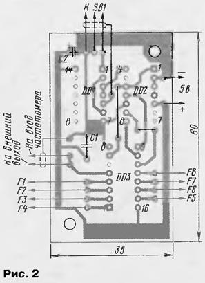
Circuit Board device and the arrangement of parts therein shown in Fig. 2. The printed circuit Board is made of one-sided foil fiberglass (Micarta) with a thickness of 1.5...2 mm. console is Powered from the PSU the frequency counter.

It should be noted that the signals from the output of the multiplexer can be coupled to the input frequency, bypassing the input of the shaper rectangular pulses, as these signals have TTL levels. In that case, if the unit has a standard frequency the number of stages of division is less than 7, it is necessary in the scheme to make some changes. For example, when using a set of four frequencies (F1 - F4) this option is possible schema changes, when each of the signals F1 - F4 served simultaneously on two inputs: F1 - to the inputs D0, D4; F2 - D1, D5; F3 - the inputs D2, D6; F4 - the inputs D3, D7.
As the rate of the console has a small size, it fits in a case the the frequency, in the vicinity of the generator model frequency. In design frequency no changes are necessary except the front panel, which establish the button SB1 and socket "Exit".
Author: W. Klapalek, senior Giaginskaya, Adygea


