It is known that the stabilizing properties of the quartz resonator is most fully implements, if he is excited at the frequency of series resonance. Author managed to develop a generator with quartz stabilization of frequency, self-excited frequency of the series resonance and almost no requiring the establishment.
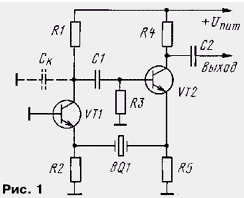
The basis was taken, the known oscillator in which a crystal oscillator is enabled between the emitter of the associated transistor cascades. His simplified scheme (without the bias circuits for transistors) shown in Fig. 1. Transistor VT1 is connected to the circuit with a common base, and VT2 - common-collector (emitter-follower). As it is known that the output impedance of the emitter follower and the input - stage a common base is very small, so the quartz resonator is included between two small and almost resistances. In these conditions, he passes the signal, closing a feedback loop, only at the frequency of your the series resonance, where the resistance is minimal.

For the self-excitation of the generator is necessary to observe balance of amplitude and phase. The first is that the product of the transmission coefficients of all the links in the feedback loop was slightly greater than unity. If it is less than this value, the generator is not smoothmedia, but if much more - 'm excited, resulting in deteriorating the stability of the frequency and the waveform (because of call to the non-linear region of the characteristics of the transistors).
The balance of the phases is that the phase shift in the ring was equal to either 0 or 360°. Otherwise, an additional phase shift will need to compensate the resonator, and in accordance with the phase characteristic of the last generator smoothmedia not exactly at the resonant frequency, and a little aloof. And what is most worryingly, this frequency shift will depend on the mode, temperature and other destabilizing factors. By the way, the frequency offset due to the skew smaller the higher the quality factor of the resonator and consequently its phase cooler feature. Because of that, and recommend the use of high-q resonators.
Run conditions described in the proposed generator helps chain R3C1, serving for connection of the amplification stage (VT1) with the emitter follower (VT2). The reluctance to use the load of the amplifier oscillating circuit has resulted in increased stress stands out rather not on active the load resistance R1 and the capacitive resistance of the collector junction. Connection point capacity of the reservoir and installation of the IC shown in Fig. 1 bar line. These tanks are similar to the integrating circuit, creating a lag phase by about 90°. Differentiating the chain R3C1 creates a phase advance for the on same angle, resulting in a complete phase shift in the ring are close to zero. Reducing the capacitance C1 can be reduced and the transfer coefficient, eliminating thus the excitement. The output signal is easy to remove from the resistor R4, included in the collector circuit of the transistor VT2 emitter repeater. Because its high output resistance influence subsequent stages in the operation generator is negligible.
Experiments with the generator described has shown that he is very snowspeeders easy, adjustments requires virtually no, for the values of parts and type transistors quite uncritically. Naturally, he generates on main the frequency of the series resonance of the quartz resonator. However, for УSW local oscillators and transmitters good harmonique generators that produce fluctuations or even triple uparennoe frequency of the resonator (by the way, and the last factor on harmonics much higher). The question arose whether to make this generator is excited at the third harmonic of the quartz? It turned out what, even despite the absence of the oscillatory circuit, it is possible! To do this take microwave transistors with high cut-off frequency (not lower than 300...500 MHz) and to reduce to a minimum the load resistance R1 and the capacitance of the separation capacitor C1. Conditions for excitation of the third harmonic are obtained by this is better than the first.
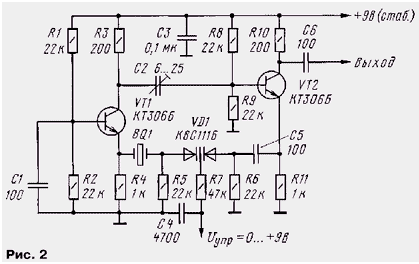
Practical oscillator circuit shown in Fig. 2

Modes of transistors DC determine the divider R1R2 and in R8R9 basic circuits. Collector current depends on the resistance of resistors R4 and R11 and equal in this case approximately 4 mA and the total current consumed by the generator - 8 mA. Selection of modes is not required. A supply voltage of 9 V, it is desirable to stabilize.
The author used the generator in widespread small quartz resonators in a metal enclosure from radio stations CBS range of 27 MHz. The frequency of the principal resonance is about 9 MHz, but on the body indicated the frequency the third harmonic. From a rather large batch of only a few resonators (approximately 5 %) had insufficient activity for the self-excitation of this generator. To adjust the frequency in small steps consistently with quartz resonator BQ 1 included Maricopa matrix VD1. When you change the control voltage I control from 0 to 9 In frequency was changed to 700 Hz. Taking into account subsequent frequency multiplication (and the deviation is multiplied as many times) enough for narrowband FM in УSW ranges. If the modulation or remote adjustment of the oscillator frequency control voltage is not required elements VD1, R5-R7, C4 and C5 can be deleted (right - scheme - the output of the resonator in this case is connected directly to the emitter of VT2). In small limits the frequency you can also adjust the trimpot a capacitor, connected in series with a quartz resonator BQ 1.
The establishment of the generator is reduced to the capacitance of trimmer capacitor C2 to obtain a stable self-excitation at the third harmonic. When insufficient generation capacity breaks down completely, and when excessive can to happen "jump" to the first harmonic. The output voltage is about 0.5 V. It convenient to control the high-frequency oscilloscope attached to the output generator.
Author: Vladimir Polyakov (RA3AAE)


