A simple modulated oscillator, which can be used for the formation and processing of various signals in the Amateur radio devices.
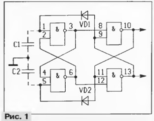
To begin, consider the scheme of the generator of rectangular pulses (Fig. 1), which made of two RS-triggers of logic elements of the IC MOS or CMOS.

The generator works as follows. When the power input parasitic capacity of each element in the diagram is conventionally shown as C1 and C2 is discharged. The initial state of inputs 1 and 5 of the first trigger signal equals the log. 0, and at the outputs 3 and 6 - log. 1. The second trigger randomly set in one of two States: suppose that output 10 - log. 1, output 13 - log. 0. In this case, the diode VD1 is closed, a VD2 is opened and quite quickly charges C2. Input 5 set log. 1, and the output 6 - log. 0, and the second trigger switches to a different state, respectively opening the diode VD1 and closing VD2. The capacitance C1 is charged through the diode VD1, and input 1 appears log. 1.
In this state, the triggers will be as long as the pin 1 is not appears the level of the log. 0. This time is determined by the input capacitance C2, a current leakage of the input* and the difference between the voltage log. 1 (approximately equal to u n and m) and the threshold voltage of the chip (about half of u pit): t = C2(u pit·Uпор)·Ileak.
After the discharge of the capacitor C2 to the threshold voltage of the second trigger again switches, again charged and C2 starts to discharge C1. Upon reaching it the threshold voltage of the second trigger again switches; in further processes again.
As can be seen from the above equation with constant current leakage and the threshold voltage of the discharge time of the parasitic capacitance depends on its size. I model sample generator, when it approached arm, was observed change the frequency and pulse ratio. To reduce the influence of the reverse current diodes they are chosen with the smallest possible leakage current (type KDA).
The pulse duration in such a generator can be controlled by changing the discharge current input capacitors logic elements. On the basis of this principle can be built generator with pulse width modulation.
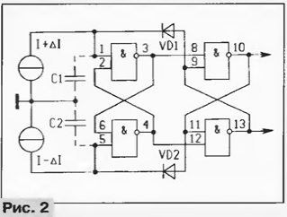
Consider this option more modulation. Inputs 1 and 6 elements DD1 connect the two current source driven with a modulated signal (Fig. 2). When change of the input signal current of one source is increased by ΔI, the other decreases by ΔI.

Accordingly, one period will be: T = t1+ t2 = S1 X Uпор/(I + ΔI) + C2 x X Uпор/(I - ΔI).
As can be seen from the formula, the larger the discharge current of input capacitors, the smaller the period and, accordingly, the higher the frequency of the modulator.
Restore the original (baseband) signal is possible using a simple the integrating circuit, the output of which is at a constant pulse amplitude (IAMP) the output voltage will be: Uвых = N x t1(t1+t2). It is easy to conclude that when ΔI = 0, the same input capacitances and threshold voltages of the inputs a logical unit at the output of the integrating circuit to apply the voltage close in magnitude to half the supply voltage. The change in output voltage and the transfer coefficient for modulating signal correspond expressions: ΔUвых = N X ΔI/2I; K = ΔUвых/ΔUвх = (N/2I)∙(2I/It) = IAMP/It, where It is the thermal voltage equal to 26 mV at a temperature of 300 K.
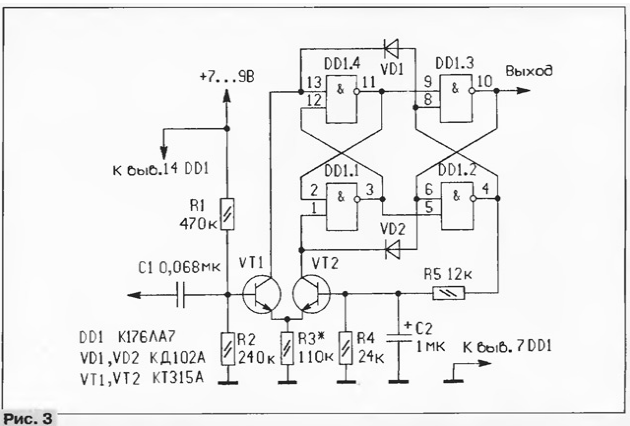
Another note. Under the action of the input signal varies as the pulse duration, and the duration of the pause. The frequency of the pulse also changes: when the increase in the input signal is reduced. This is enough large dynamic range of the device. Practical oscillator circuit shown in Fig. 3. The elements chosen for reasons of accessibility and the repeatability of parameters.

Input differential cascade (VT1, VT2) is made on bipolar transistors KT315 (with any letter index), preferably with close transmission of the base current. As the diodes used CD with a small reverse current. To increase the stability of the generator in the scheme introduced negative feedback from the output 4 via a low-pass filter from resistor R5, capacitor C2 and resistor R4 with a cutoff frequency of about 16 Hz.
Setup generator is made by selection of the resistor R3 to the desired frequency modulation.
Author: V. Humpback, Ulan-Ude


