


")

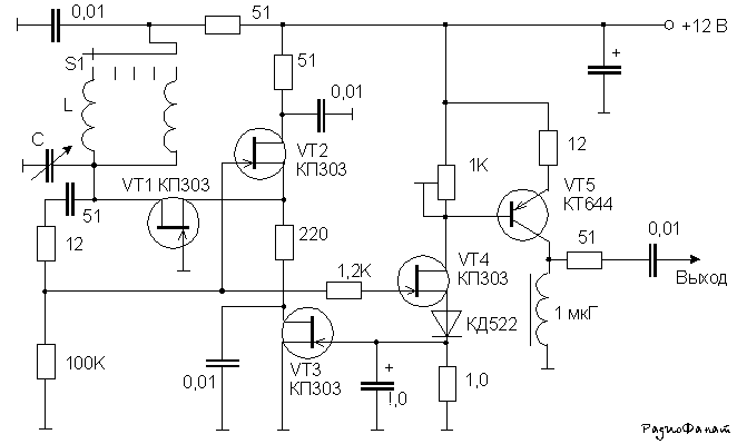
The scheme has good stability of both frequency and amplitude signal. Actually the generator is made on transistors VT1-VT2. Transistor VT3 is the stabilizer of the signal amplitude. On VT4-VT5 made buffer amplifier. A variable resistor is adjustable the amplitude of the output signal. Data circuits are selected according from the frequency range.
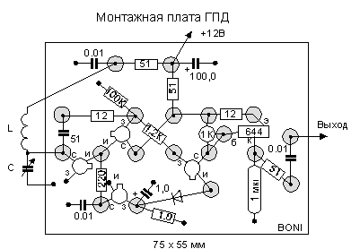
Installation is performed on the "patch" technology Zutaeva. Better, of course, to perform it with the ceramic panels to the uprights.
P. S. me Personally, this scheme is tested in the range from 5 up to 24 MHz as the master oscillator of the transceiver. It should be noted the distortion of the output waveform when reducing the amplitude of the output signal.
Author: Nikolay Bolshakov, rf.atnn.ru