


")

As neperestavaya local oscillators for converters range 144-146 MHz is usually used vacuum-tube or transistor oscillators stabilized by quartz, generating in the range of 10-50 MHz (crystal oscillator this brought on the third to the fifth mechanical harmonica), and two or three of the cascade frequency multiplication. At the same time, single-stage transistor oscillator stabilized by quartz at higher (up to ten) mechanical harmonics have a number of advantages: absence in the spectrum of the signal of low-frequency harmonics with sufficiently large amplitudes; small size, allowing full screen and fairly simple means thermostated block local oscillator; low-temperature instability of the amplitude of the output signal (due to the presence of a minimum number of narrowband circuits); greater reliability (fewer features).
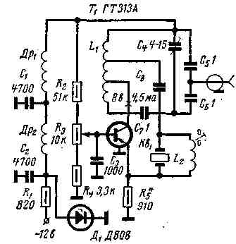
Practical circuit of the local oscillator at the frequency of 115 MHz, designed for Converter band 144 - 146 MHz intermediate frequency 29-31 MHz, is shown in the figure. It is assembled on the transistor T1 connected in the circuit with a common base, with a quartz resonator in the chain of positive feedback between the collector circuit and the emitter circuit. Such a stable oscillator generates frequencies up to 250-300 MHz. For optimal condition excitation and maximum stability of frequency generation the coefficients of the enable transistor and quartz in the collector circuit of the selected respectively equal to 0.65 and 0.25.
Designation scheme
Inductanceefficiency,
MH
AddRottnest
Wire
Frame
Step winding,
mm
The number
turns
DR1, DR2 DO
1,3
PELSHO 0,12
Resistor MLT-0,5,
0,2
27
1 MW
L1
6
50
silver plated
ceramic dia
1.2
20
0.64
meter 18 mm
L2
0,3
25
PELSHO 0,25
ceramic dia
0,5
6
meter 6 MM
Quartz is enabled through a capacitor C8 (15pF). Parallel to the quartz resonator included the inductor L2, compensating the static capacitance of the quartz. The generator is excited at the seventh mechanical harmonic of the quartz resonance frequency of 16.44 MHz. The amplitude of the output signal reaches 120-140 mV. It's also possible the excitation of the oscillator at the eleventh harmonic (quartz resonator should be with the resonance frequency of 10.45 MHz), however the amplitude is somewhat smaller additionally, the complicated setting of the oscillator: it becomes critical to even a small nastroika collector and compensating circuits. The design of the local oscillator used in an efficient isolation of power circuits using a double l-shaped LC filter protective. The output of the oscillator is designed to connect a standard 75-Ohm coaxial cable and has a partial capacitive coupling with the collector circuit.
Consumed by the local oscillator on the supply capacity of 60 MW. Details and design determine the frequency stability of generation to the same extent as the selection scheme. Therefore, in the design it is advisable to use fixed resistors MLT-0,5 (or MLT-0,25); resistor R3-CSP-0,15; capacitors C1 and C2 - CSR, CMB or K10-7V, C3-CSR, CMB, C4-CPC 1 or CPC-M; contour capacitors and capacitor C7 - CT-1, preferably C5 and C6 to bring positive TKE (group P, blue or rltb grey body), and C8 - negative TKE (ARIES group, M47 - blue color, respectively, with brown or red dot). These coils and chokes are shown in the table. Coil L1 is placed in an aluminum screen sizes HH mm Taps, counting from the upper circuit on the end, from the fifth round to the capacitor C8 and the thirteenth coil - to the collector of the transistor T1.
The structure is made in the form of a block on a separate (from the Converter) chassis dimensions HH mm Heterodyne configured using the tester, УSW HSU and HF vacuum tube voltmeter. The selection of the resistance of the resistor R5 sets the emitter current equal 2-3,5 mA (or more), before the emergence of stable generation. Resistor LZ choose the voltage at the base of the transistor T1. Further trimming of the core of the coil L2 set up a compensation circuit. Then tune the collector circuit at a frequency slightly higher (500-600 kHz) generation frequency - the frequency stability of the oscillator will be minimal.
The outlet from the coil L1 to enable the collector of transistor T1 is selected within 11 and 15 round - until a stable generation Next in an already configured the oscillator can clarify the capacitance of the capacitor C7, by varying it in the range of 5-25 pF and the pursuit of a more sustainable generation, the maximum allowable nastroika collector circuit. (This detuning when using seventh mechanical harmonic quartz can reach values of the order of 1 MHz). The maximum amount of detuning compensation circuit is 250-350 kHz.
Literature
Publication: N. Bolshakov, rf.atnn.ru