


")

Communication device (Fig. 1)
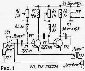
The heart of this device the amplifier of sound frequency in two the transistors connected in the circuit with common emitter. To be exact to establish the optimal mode of operation, in the circuit of the bases of the transistors included variable resistors (R1 and R4).
Communication device is equipped with two primers from headphones TONE-2 - BF1 and BF2. The first of these may be found near the amplifier, together with the second push-button switch SB2 is removed at the right distance and connected to the amplifier three wires.
In the diagram shows the position of the moving contacts of push button switches SB1 and SB2 capsule is set to accept messages. If a subscriber with primer BF1, press the switch button SB1, the cap of the BF1 will be connected to the input of the amplifier and the conversation will be heard by the owner of the cap BF2. Similar the second way, the subscriber can send a message first if you push the button SB2 (button SB1 must be released).
To establish the amplifier easier Pataskala, starting with the cascade transistor VT2. This left circuit output capacitor C2 is disconnected from the manifold transistor VT1 and include between this pin and GND primer BF1. Asking someone to speak a few phrases before primer BF1, listen the sound in the earpiece BF2. Moving the slider to the resistor R4 to achieve this highest volume and lowest distortion.
Similarly, set the operation mode of the transistor VT1 variable resistor R1, connecting the capsule BF1 to the left on the diagram the output of the capacitor C1 or clicking on button SB1 (connection of the capacitor C2 to the collector of the transistor VT1 need of course, to restore).
To establish the device using a DC voltmeter, connected to the terminals of the emitter and collector of transistors. Relevant the variable resistor sets the voltage at the collector of about 6 V.
The generator of sound frequency (Fig. 2)
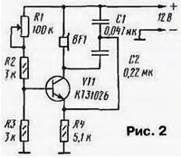
It is made up of only one transistor. The headset TONE-2 (BF1), capsule which it is desirable to include in series, and capacitors C1, C2 form a the resonant circuit. To have any generation, the bypass circuit is connected to the emitter of transistor cascade is a chain of positive feedback.
The frequency of the generated oscillations depends on the values of the capacitors of the circuit and entered the resistance of the variable resistor R1. Listening to the sound in the phones, make sure to change its pitch when you move the cursor of the resistor. If it is possible to change the supply voltage (to reduce it to 3 In), it is easy to notice, and its effect on the oscillator frequency.
Multivibrator - "the flasher" (Fig. 3)
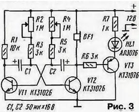
If two of the amplification stage, for example, depicted in Fig. 1, to connect between themselves so that the output signal of each received input to another, will receive the pulse generator is called a multivibrator.
Our experimental multivibrator is supplied headphones BF1, using which listen to the sound. It you can change the key variables resistors R2 and R4. Moreover, it will be perceived as different clicks repetition rate - depending on the position of the sliders of variable resistors.
To better show the operation of the multivibrator, it is complemented with light the device, made on the VT3 transistor. In the circuit of emitter included led HL1. Now the clicks will be accompanied by flashes led. Their brightness is set by resistor R7.
The led flashes can be seen that the resistor R4 affects not only the frequency pulses, but also on the duration of the flash, a R2 - pauses.
Moving the sliders of variable resistors it is possible to achieve the same durations led flashes and pauses between them.
Siren (Fig. 4)
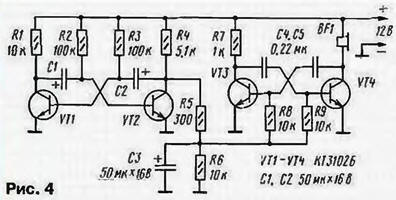
The structure is made of two multivibrators. One of them (transistors VT3, VT4) is designed to receive the audio frequency of about 1000 Hz, the pulses of the other (on transistors VT1, VT2) followed by a frequency of 0.5-1 Hz. Because the output of the low-frequency generator connected to the frequency control input of the more high frequency, in the head phones you can hear the signal is changing frequency from 500 to 1000 Hz. These abrupt changes - when you open the transistor VT2 the sound of one tone, and when closed is another. Smoother changes frequency can be achieved by setting the resistor R5 greater resistance.
To the sound of a siren was louder, blasting headphones TONE-2 should be connected parallel.
Turn indicator for a Bicycle (Fig. 5)
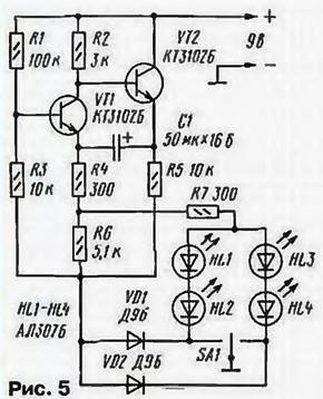
The heart of this device is a pulse generator, transistors VT1 and VT2. The pulse repetition rate depends mainly on the capacity of the capacitor C1 and the resistors R4 - R6.
While the movable contact of the switch SA1 is shown in the diagram position the generator is not working, because it is not served supply voltage. It is worth to move the movable contact to the left on the diagram, the emitter circuits of transistors will be connected to the common wire (minus voltage power). At the same time in the emitter circuit of the signal will be included LEDs HL1, HL2, which will start flashing.
When the movable switch contact is moved to the right under the scheme the voltage at the generator will go through the diode VD2, and flashing LEDs will be HL3, HL4.
If you wish to install such a facility on your bike, LEDs should be attached to the flaps of wheels: HL1 and HL2 left of the wheels (respectively the front and rear panels), and HL3 and HL4 - right.
Acoustic relay (Fig. 6)
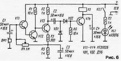
So we call a device that "works" with sound (loud voice, clapping, etc.) and includes a load, e.g. a lamp.
Acoustic relay consists of a microphone VM (it is the role of the head cap phones TONE-2), the sensing amplifier of audio frequency transistors VT1 - VT3, detector diodes VD1, VD2, an electronic key on the transistor VT4 and electromagnetic relay K1. The relay contacts K1.1 in the circuit of the light alarm triggering devices - LEDs HL1. The mode of operation of the amplifier set the variable resistor R4.
While there is no audio signal, the transistor VT4 is closed, the relay is deenergized. Enough to speak close to the microphone, say, loud, as the amplifier will go the audio signal. From the output of the amplifier it will be served on the detector. Appearing at the load detector (resistor R6) signal in the form of a unipolar pulses of long duration will open the transistor VT4. Work relays and their the contacts provide power to the led. Brightness it is limited by resistor R7. After the cessation of the audio signal relays for some time continue to keep the charging current of the capacitor C4, and then let go. The led will turn off.
Relay - reed RASA, passport RS4.569.600-10. The impedance of 377 Ohm scatter ± 56,5 Ohms, the voltage is 5.9 V, working voltage is 10 V.
Establishing relay start with checking the output stage - the electronic key. When connect the resistor of 10 ohms between the positive of power supply and the base of transistor VT4 should trigger the relay K1 and to light up the led. Then pronounce some sounds or phrases near the microphone and see again the ignition of the led. Displacement engine variable resistor R4 achieve the greatest sensitivity to acoustic relays respond to the voice with perhaps a greater distance from the microphone.
Time relay (Fig. 7)
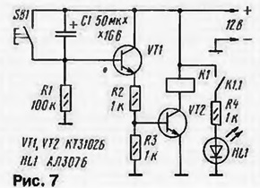
It is known that if you connect a discharged capacitor to the power source through it begins to flow the charging current. As the charging of the capacitor this current decreases and stops when the capacitor is fully charged. The charging time depends on the capacitance and resistance of the circuit, to which it is connected.
Built on this principle our relay that allows you to count down the set time. As in the previous device, it uses an electronic key on the transistor VT2 and light alarm led HL1. Cascade transistor VT1 - current amplifier.
Once the device is connected to the power source, the charging begins capacitor C1. Immediately opens both transistors, electromagnetic work relay contacts K1 and K1.1 turn on the led. As the capacitor charging current through the transistor VT1 will begin to decrease and the voltage across the resistor R4 and, hence, on the base of the transistor VT2 will fall. After a certain time, which depends from the capacitance and resistance of the resistor R1, the time will come when both transistor is closed, the relay K1 is released, the led will turn off.
For subsequent start time relay short enough to press the button SB1 to discharge the capacitor. Relay K1 is the same as in the previous design.
Time relay can be used, for example, in alarm. It will be be included at the time of entry to the protected area or to exit the utility .
Touch switch (Fig. 8)
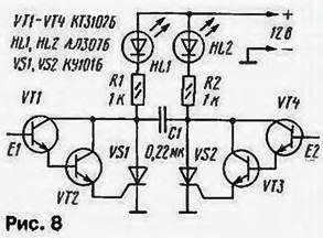
So-called contactless electronic switch that is triggered when a finger is touching special sensitive (touch) pad, or just the sensor. I switch two channels, each of which consists of a composite transistor, assembled from two bipolar, SCR (VS1 - in-one "channel" and VS2 - in friend) and led indicator.
SCR has three electrodes the anode, cathode, control electrode and has an interesting property: if a short to submit to the control electrode switching voltage, in other words, skip the current through the circuit control electrode - the cathode, the SCR will open and will remain in that state until he'll beat anode voltage or shorted conclusions of the anode and cathode.
When you touch your finger to the sensor E1 is the composite transistor, it open. Flowing through it and the control electrode of SCR VS1 current leads to the opening of the SCR. Lit led HL1, a HL2 remains repaid. The capacitor C1 is charged so that its right-hand circuit on the output plus voltage, and on the left - minus.
If you now touch the sensor E2, opens a composite transistor VT4 VT3, and in the Wake of SCR VS2. The capacitor will be connected between the anode and the cathode of SCR VS1 in reverse polarity, i.e., a minus to the anode that equivalent circuit of the electrodes. HL1 led is off, a HL2 - lit.
Some instances of triacs are not held in the open state due to insufficient anode current. Then you have to increase the current connection parallel readout circuit constant of the resistor. For example, in our case between the bottom under the scheme the output resistor R1 and a plus power source, if not retained SCR VS1.
Combination lock (Fig. 9)
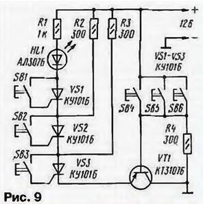
This lock can be found, say, on the doors of houses, apartments, laboratories in other places, where the entrance to unauthorized persons should be limited. Automation lock only works when pressed in a certain sequence several buttons on the remote. If it succeeds, the lock work and open the front door.
The proposed layout of the castle contains three "correct" button (SB1-SB3) and the same "fake" (SB4-SB6). In the initial state, the transistor VT1 is open, triacs VS1 - VS3 are closed. "Program" of the lock is made so that first need to click on button SB3. Open SCR VS3 and will remain in this condition because in its anode circuit is the load (resistor R3), providing the desired current hold.
Next you need to press the button SB2, to trigger SCR VS2 (load - the resistor R2). Last press the button SB1. Open SCR VS1, lit HL1 led, signaling correct operation of the automation. Usually it is the actuator - solenoid nominating the latch or electromagnetic relay that supplies voltage to the solenoid.
If these buttons to push in a different order to open the lock will fail. When random clicking at least one button of SB4-SB6 closes the transistor VT1 and will remove power from the triacs is already opened will be closed.
The more buttons "right" and "fake", the greater the secrecy, the harder to crack the code and open the door.
It may happen that SCR VS1 will not be charged after opening. Then you should use the recommendations for the previous design and increase the anode current by connecting the resistor of 300 Ohms between the cathode of the led and a plus power source.
Author: A. Partin