


")

The details of the set (Fig. 1)
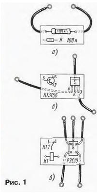
Every detail of the feature set on a small strip corresponding to the dimensions element. Straps can be made of Micarta, textolite and even tight cardboard. The elements are fixed to the slats of their findings (Fig. 1 ,a) to which solder the conductors of the stranded mounting wire in isolation. The wire ends obluzhivayut and bend the ring under the screw diameter of 3 mm. Even better to solder to the ends of the conductors of the finished petals. The transistors (Fig. 1,6). relay (Fig. 1.in) and other items may simply be glued.
On the strap is applied to the graphic symbol of the element, indicate the type or the face value. This solution has didactic value is visible on planks the parameters of all parts, which are then placed on the circuit Board according to typeface concept.
Circuit Board (Fig. 2)
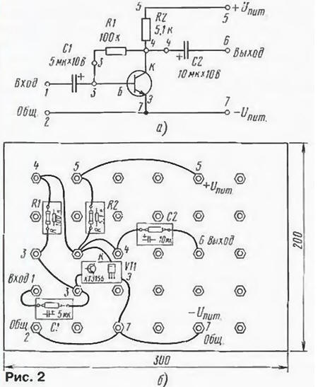
It can be made of any insulating material or plywood 2…3 mm and a size of 200x300 (250x350) mm. On it in 5-6 rows of drilled holes 3 mm diameter, into which insert the bottom screws with a length of 20 mm and fix them top nut (between the nut and the Board it is desirable to lay the washers). On the protruding ends of the screws when mounting the device impose the findings of items (not more than four) or the ends of the connecting wires (supplied in kit) and firmly tighten the nut. Example of installation single-stage amplifier CC (Fig. 2,a) on the circuit Board shown in Fig. 2,b.
The set radiokonstruktor may include 2-3 of these fees so that you build more complex devices.
Now let's look at some designs that are offered for build novice radio Amateurs.
Test transistors and diodes (Fig. 3)
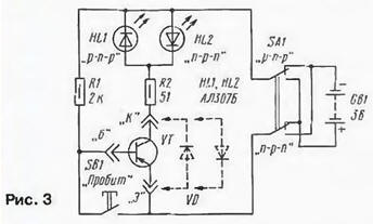
Before you put these details to collect design, you should make sure that they not out of order after work in the previous device. The tester can collect in a separate unit or be mounted on one of the circuit boards.
If the findings of the transistor is connected to the terminals "a", "B". "To" is correct, but movable contacts of the switch SA1 is located in a position corresponding to the structure of the transistor, should illuminate one of the LEDs. When you click on the button SB1, the led will turn off. Other options reaction LEDs indicate malfunction of the device - the breakdown of transition or break in the circuit some of the output transistor.
Check the diodes include in the nests of "K" and "e". About the serviceability of the diode will signal the lightened led HL1 or HL2 depending on the situation of switch contacts and polarity of the outputs of the diode.
Sound "watchman" - a tone generator (Fig. 4)
This design can serve as a simple watchdog and the tone generator - simulator sounds, musical instrument (EMR). On two transistors assembled generator that is not working, while to the terminals X1, x2 connected serviceable protective loop of thin copper wire, laid on the perimeter of the area. Once the integrity of the wires is broken, will come into the action generator, headphones (earpiece type TA-56M resistance 45-60 Ohms) BF1 will hear the sound, the tone of which depends on the values of parts R1, C1. Connecting to the jacks XS, X4 resistors to 510 ohms, and to jacks X5. X6 capacitors of 0.1 µf, you can change the tone sound widely.
If you pick a few different impedance resistors and connect them to jacks XS, X4 using button that will get the simplest AMY - pressing, it is easy to pick up a tune.
To terminals X1, x2 is possible to connect a ribbon cable reed switch or the contacts installed, say, on the door of the protected premises (if few contacts, they include a series).
Multivibrator - "the flasher" (Fig. 5)
The heart of this device is symmetrical multivibrator, transistors VT2, VT3. The pulse repetition rate of the multivibrator depends on the values of resistors R2, R3 and capacitors C1, C2. The pulses of the multivibrator are served on amplifiers current collected on the transistors VT1, VT4. In the collector circuit of each transistor (terminals X1, x2, and X3, X4) are permitted to include a relatively powerful lamps HL1 and HL2 of the 6.3 V or two series-connected on voltage 3.5 V, when the battery is used GB1 voltage of 6 V. source another voltage applied appropriate combination lamp on. Instead lamps suitable LEDs HL3, HL4.
One of the practical applications of such a multivibrator - turn indicator for bike. However, instead of the switch to install the switch with two sections of switching contacts and with the average position of the control knob. In each of the extreme positions of the handle one section to supply power to device, and the second is to enable one pair of signal lights (right turn), or another (left turn).
A DC amplifier (Fig. 6)
He made three transistors and has a high sensitivity. If its input terminals X1, x2 to connect the photoresistor or photodiode (anode to the clamp X2), the device will turn into a photosensor. Under the illumination of the photoresistor beam flashlight or other light source will begin to open transistors and to ignite the lamp HLT connected to the terminals XS, X4.
Replacing the input terminals of the metal strips contacts, get touch switch. Artistic contacts, will be able to light a signal lamp.
You can use the relay to control a more powerful light source, say, lighting a lamp is a 12 volt, powered by a rechargeable battery or the network rectifier. You have to connect to the terminals XS, X4 electromagnetic relay K1 type RAS passport RS4.529.031-08 or RAS passport RS4.529.029-12. Closing the relay contacts include in series with the load, this case lamp.
Time relay (Fig. 7)
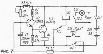
Condenser time relay can be used as a timer for photo printing. It insures (includes lamp EL1) from a few seconds to several minutes depending on the resistors R I. R2 and capacitance capacitor C1 (can be up to 2000 μf).
After power-up switch SA1 transistors are closed, the relays K1 and K2 de-energized. The relay is ready for operation. Button SB1 triggers relay K2. Contacts Of K2.1 it is self-locking (the button can be released), and contacts of K2.2 serves the voltage on the lamp EL1. Begins exposure - via the resistors R1, R2 is charging the capacitor. As soon as the voltage across it reaches a certain value will trigger relay K1 and its contacts K1.1 disconnect the relay coil K2 from the power source. Contacts Of K2.1 and K2.2 return in the initial position. The lamp turns off, the capacitor is discharged through closed group of contacts K2.1 and a resistor R5. Time relay switches expectations.
Shutter speed set steplessly variable resistor R1. and abruptly - the connection of resistor R2 and capacitor C1 of other denominations. To calibrate the scale of the variable resistor is not difficult with the stopwatch.
Simulator Canary trills (Fig. 8)
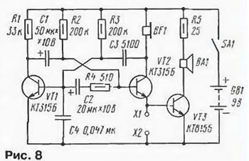
A similar device was described in the magazine "Radio". But members of the Association "Electronics" slightly modified it by typing the capacitor C4 and adding a power amplifier transistor VT3, the dynamic head of BA1 and limiting the volume of the resistor R5 (it consists of two parallel United resistors 51 Ohm). Sound simulator was fun.
If you short circuit the terminals X1 and x2, trills will be distributed only in phone the primer BF1 (type TA-56M). When will be opened by the said clamps, you hear a louder sound from a dynamic head of BA1 (any head with a capacity of 0.25 to 1 W with a voice coil impedance of 8 to 10 Ohms). In this version simulator is able to perform the role of housing call, if instead switch to connect it to the outer bell button.
The selection of elements C1 - C3, R4 can change the tone, the duration of trills and pauses between them.
Simulator sounds "meow" (Fig. 9)
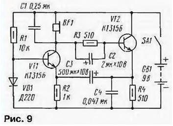
This simulator is able to produce sounds resembling the mewing of a kitten. Thanks entered the chain R3C2 sound more natural. If desired to experiment with the simulator it is recommended to install the parts C1, C3, R2, R4 of different denominations.
Universal simulator (Fig. 10)
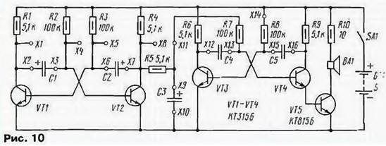
Its design is based on dual tone siren and consists of "slow" (low the pulse repetition rate) of the multivibrator transistors VT1, VT2, sound (transistors VT3, VT4), and the power amp on transistor VT5. Chain R5C3 - integrating, allowing you to smoothly change the frequency of the second multivibrator.
When the values of capacitors C1 - 10 UF. C2 - 20 µf, C3 - 200 µf, C4 and C5 0.01 µf as shown in the diagram the connections of the simulator provides a sound alarm sirens. However, if changing the value of capacitors C1, C2 from 0.5 to 100 µf, C3 - from 20 to 500 µf. C4, C5 - 0.01 to 0.5 µf and rearrange the wires from upper circuit of the terminal of the resistor R7. R8 to the terminals X1. X4, X5, X8, X11, x14 in different combinations, can get dozens of different (sometimes very unusual) soundings. This bird trills, the noise of a motorcycle, the sound of "tremolo", "snoring" and many other. The sound can further diversify by changing the supply the voltage in the range 2…9 V.
By conducting these experiments, it is desirable to connect to the specified terminals of the oscilloscope, to watch the changing of the shape oscillations.
Author: M. Erofeev