


")

The proposed generator is useful for Troubleshooting various electro-acoustic equipment. It allows you to supply voltage sound signal in different points check the device, ranging from MIC the entrance, and, thus, to find the broken cascade or channel stereo apparatus.
The generator provides the output rectangular pulses with a duty cycle 2 (meander) and medium frequency sound range (1000…1200 Hz). Their amplitude fixed: 1 mV, 100 mV or 0.7 V. To control the stereo generator has two outputs with independent enable signal. The amplitude of the signal at two outputs the same.
The rectangular shape of the signal allows, in the presence of an oscilloscope, to judge amplitudemodulated and phase-frequency characteristics of the device, and the propensity to self-excitation [1].
The oscillator circuit shown in Fig. 1.
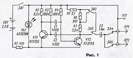
The generator is built on a symmetrical multivibrator [2] on transistors VT1 and VT2. Transistors it is desirable to select with the current transfer ratio of not less than 50. The frequency of oscillation is determined elements R3, R4, C1 and C2. The collector load of the second transistor is composed of of the three resistors forming the divider output voltage. The switches SA2 and SA3 set the amplitude of the output voltage, switches SA4 and SA5 the signal is fed to the desired output. As the switches used tumblers type MT-1.
Led HL1 performs several functions: together with the resistor R1 it stabilizes the voltage of the multivibrator indicates the inclusion generator and battery status. Reducing the brightness of its light indicates that the battery time to charge.
Powered generator from two disk batteries of type D is 0.25. This provides clean output signal without any impurities and background AC current. With the same purpose, the generator is placed in a metal case, and the weekend wire with shielded probes.
To charge the batteries is used a device, scheme of which is shown in Fig. 2.
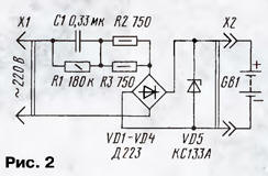
The quenching capacitor C1 in an AC circuit limits the charging current to acceptable level, and the resistors R2 and R3 limit the possible inrush current during on and voltage drops in the network. The Zener diode limits voltage VD5 the output of the charger if any contact with the battery or if the erroneous inclusion in the network without batteries.
The design of the charger should avoid contact with hands any live conductors. Capacitor C1 (type K73-17 or MBM) is selected on the operating voltage of not lower than 300 V. the Rectifier bridge can be used ready, for example, type CCE. The charging time of the battery - 15 to 20 hours.
Most of the detail of the generator is mounted on a circuit Board from unilaterally foil fiberglass, a sketch of which is shown in Fig. 3.
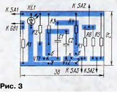
The fee is not has holes - the findings of the details are superimposed on the traces, and soldered to them. The conductive tracks can be cut with a sharp knife or the cutter along the ruler without resorting to etching. Unnecessary foil between conductors is removed by any method, for example, by using the same knife. To facilitate this the foil is useful to warm up the soldering iron.
Manufactured printed circuit Board is placed in a housing of appropriate size, made of any material. In the author's version was used metal box size 100x60x30 mm, covered with a decorative film. On the upper lid, there is a power switch and switches SA1 weekend signals SA2 - SA5. Output terminals 1, HR and suit any XP2 can do do without them, bringing the three output wires through the hole in the side wall of the housing. The wires must be terminated by probes or clamps type "crocodile".
Build the generator, collected from the healthy parts, requires little or no, begins to work immediately. Optionally, you can set the frequency of oscillation matching capacitors C1, C2 and resistors R3, R4. It is also useful to adjust the levels of output voltages, selecting resistors R5 - R7.
Literature
Author: I. Gorodetsky, Moscow