


")

Barrier transistor operating mode provides the important property that the wide variation of values of L and C in such generators does not lead to noticeable changes in the level of the output RF voltage (0.5 to 0.6 V for silicon and 0.2-0.3 V for germanium).
At first glance, the advantage of generating the RF voltage less than 1 V is not so essential, but it increases the frequency stability (both short-and long-term). In addition, it is possible to use to rebuild variely that at low RF voltages to a much lesser extent degrade the frequency stability of the generator.
In [1] essentially provides a barrier circuit of the differential amplifier, and in [2] provides a brief definition of barrier transistor operating mode without detailed analysis. In this regard, let us consider some of the important features of barrier mode of operation of a bipolar transistor in which the base of the transistor DC-connected circuit or through a resistor with a small resistance to the collector (Fig.1). The power to the circuit is supplied through a resistor that sets the current through the transistor, i.e. no usual chain offset.
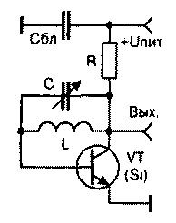
Fig.1
Transistor inclusion in barrier is a kind of diode, connected in series with dakotadome resistor. Since the voltage "emitter-base" for framemaster p-n junction is approximately 0.6. .0,7 for silicon In transistors and 0.3…0.4 V for germanium, the potential of the reservoir and equal to this value. When the saturation voltage of about 0.1 In the maximum amplitude of the output RF voltage for circuits with silicon transistors will be about 0.5…0.6 V and about 0.2…0.3 V with germanium.
The current flowing through the transistor, can be approximately estimated by the formula I=(u pit-(0,6…0,7 (B))/R(A), where u pit - voltage, V; R - resistance dakotadashako of the resistor in Ohms. In the scheme of the generator in Fig.1 remove the RF voltage and the other end of the coil. However, this scheme has a major drawback: LC-circuit nor one of its ends not connected to ground, making it virtually impossible to frequency by using a variable capacitor. The author proposed a scheme with grounded capacitor (Fig.2). Generation will arise in case With insert between ground and base (transition "base-emitter" is open and has a very small resistance). Such a scheme, the author has successfully used as the master oscillator of a simple FM wireless microphones. Modulation was carried out using waikamoi matrix SWС111.
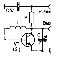
Fig.2
However, to generate a frequency with high stability, it is desirable to ground and one end of the L, which is implemented by the author in the scheme in Fig.3, where the RF voltage can be removed and with L.
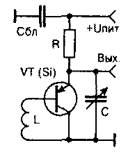
Fig.3
Note that the change of supply voltage (unless it is less than 1 In) at the same value of R still influences the frequency of the generated oscillations. For reliable operation of the transistor at higher frequencies it is necessary to increase the flowing current by reducing V. When using CTA, CTA when u pit=12 V and R=2200 Ohms steady operation of all the above schemes, at least up to 110 MHz. These schemes have high impedance outputs and need a high quality buffer stage and (or) in the removal of the RF voltage with 1/8 1/10…part turns L (counting from the grounded end), otherwise the inevitable instability of the frequency when the load resistance changes. Reactance Srls at the operating frequency should be less than 1 Ohm.
Literature
1. Titze U., Schenk, K. Semiconductor circuitry. - M.: World; 1982, p. 297
2. Stasenko V. barrier transistor operating mode.- Ham 1996, No. 1, pp. 15-17.
Author: Vladislav Artemenko, UT5UDJ, Kyiv; Publication: N. Bolshakov, rf.atnn.ru