


")

Antenna analyzer firms MFJ is widespread in Amateur radio practice. Released several modifications (see, for example, "Radio", 2000, № 5, p. 78,79). One of the features of these devices is they used RF generators with a very stable output voltage. This makes it sufficient for Amateur radio practice precision, without preliminary calibration of the apparatus, to measure VSWR and other parameters antenna-feeder tract. This RF generator analyzer overlaps ( multiple sub-bands) frequency band from 1.8 to 170 MHz.
They have another interesting feature. This is digital signal processing (in the calculation of VSWR, input impedance feeder, etc.) used in the last models of analyzers. It assumes a linear rectification of small RF voltages. What circuit solutions provide this figure illustrates, on which shows a portion of schematic diagrams of the antenna analyzer model MFJ-259B. To stabilize the output voltage of the generator linearity of the rectifier is not principled, but they are all in the device assembled according to the same scheme.
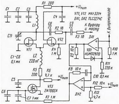
RF generator assembled on a microwave field-effect transistors VT1 and VT2 are well known the radio circuit with a source link. The use of field and not bipolar transistors (emitter coupled) provides a minimum load oscillating circuit and the relatively high stability of the oscillator frequency. If you change the ranges are switched inductors (the diagram shows one - L1) and "pulling" capacitors to KPE (C11). In the circuit source transistors VT1, VT2, in addition to the resistor R5 introduced the inductor L2, which increases the upper the boundary of the stable generation of up to 170 MHz.
For effective stabilization of the output voltage of the generator into the circuit the origins of transistors has also introduced a field-effect transistor with insulated shutter VT3. Voltage to the measuring bridge of the instrument, controlled rectifier, assembled on the high-frequency Schottky diode (for the figure not shown). Rectified voltage of positive polarity is supplied on linearizing the cascade operational amplifier DA1.
The linearization provides a high-frequency Schottky diode VD1 in the circuit negative feedback op amp. The main two requirements for this diode: he must be the same type as that of the diode rectifier and, moreover, "paired" to that the diode. In other words to have a close voltage-current characteristic. In this case the drop in efficiency of rectifying the RF voltage will be with sufficient accuracy be compensated by the increase of the transmission factor of the cascade at the shelter DA1. With it output control voltage is fed via an integrator at the shelter DA2 on the shutter regulating transistor VT3.
The efficiency of this system is the automatic level adjustment is very high - voltage on the measuring bridge practically does not change when the load changes in the measuring circuit against short-circuit to no-load stroke. The word "almost" means that it lies at the limit of its registration analog devices.
Good isolation between the generator and the measuring bridge antenna analyzer provide two buffer stage: source and emitter follower.
Author: E. Luksha (UA3AJV)