


")

Oscillators on CMOS chips popular with radio Amateurs. They are used in the design of measuring instruments, generators, audio frequency probes to check the operability of radioactive elements and stages of radio equipment. In the article described three options such generators to be made in the form of probes to verify and establish the low-frequency and high frequency components different instruments.
Usually when designing probes and calibrators used generators short pulses, resulting in a signal with a wide and uniform range. Such a signal allows you to quickly check the stages of radio equipment, as low-frequency (LF) and high frequency (HF). The smaller the duration pulses, the better spectrum obtained wider and more evenly.
Typically, these generators consist of two main components: the actual the generator of rectangular pulses and the shaper short pulses. Meanwhile you can do without a special driver, because he is already in logical element chip CMOS structure.
Consider for example the diagram of the probe shown in Fig. 1. This is a known RC oscillator operating in this case at a frequency of about 1000 Hz (it depends from details of the values of R1, C1). Low frequency square wave signal comes from the output of the element DD1.2 (pin 4) through a chain of alternating R2C3 the resistor R4 is they smoothly adjust the amplitude of the signal applied to check the node.
The same high frequency output signal (short pulses) made several unusual signal is removed from the variable resistor R3 in the circuit of the power chip. Displacement engine this resistor smoothly regulate the level output high-frequency signal.
Consider the principle of operation of such a generator, according to the simplified scheme logic element structure of the mos (Fig. 2). It is based on two cascaded field effect transistor with insulated gate and different types of conductivity channels.
If in series with the transistors include a resistor R1, and the input element to apply rectangular pulses U1, the following will occur (Fig. 3).
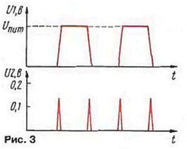
Due to the fact that the duration of the pulse front can not be infinitely small, and also because of the inertia of the transistors at the top and the front will come like this the moment when both transistors are in the open state. Through them will flow the so-called pass-through current, the value of which can range from units to tens of milliamps depending on the type of chip and the voltage source power. The resistor will be formed short voltage pulses U2. Both at the front and bust. In other words, will happen doubling the frequency of the source pulse.
The resistance of the resistor must be large to avoid violations of of the elements of the chip. This means that to a high frequency output can to connect a low-impedance load impedance of 50…75 Ohm.
I considered the generator of the maximum amplitude of the pulses at high frequency the output is 100…150 mV, and consumed from a power source current is not exceed 1.6 mA. The generator is designed for use when testing amplifiers 3H, techprogram loudspeakers, radios band LW and ST, To check out the LW nodes and УSW receivers and calibrate their scale, quite collect the crystal oscillator in the circuit shown in Fig. 4.
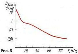
It is built on described above, but the generator operates at a frequency of 1 MHz. Short the high-voltage pulses are generated across the resistor R3 and served through a capacitor C3 to check the cascades. The dependence of the amplitude of the harmonics from the the frequency is shown in Fig. 5 - it decreases from 20 mV at a frequency of 1 MHz to 12 ICD at a frequency of 80 MHz. in most cases, it helps to perform standing before the probe task. Exactly the generation frequency set selection capacitors C1 and C2. From the power source, the generator consumes a current of about 5 mA.
On one CMOS chip it is easy to collect a combined generator - combination two constructs (Fig. 6). It also contains two outputs, and modes of the work set by the switch SA1.
In the lower circuit on the position of the movable contact of the switch only works generator bass, so the bass output will be a rectangular pulse, and the output RF - short pulses with a spectral width of up to 1.5 MHz. The average position works only crystal oscillator and the RF output will be a signal with width range up to 80 MHz. At the same time at the output of the low frequency signal is absent. If the movable switch contact to move to the upper position in the work turn on both generators, and quartz will be modulated by a signal the low-frequency generator.
When a high q quartz resonator RF generator can be bad be modulated by a signal generator LF. In this case, you need to disconnect pin 5 element DD1.3 from the switch and connect to pin 6 and to the switch to sum up the wire from pin 8 (disconnect it from the terminals 4 and 9 and the resistor R5).
Design of all generators-probes can be any, but for their sustainable work connections between parts must be perhaps shorter.
Author: I. Nechaev, Kursk