


")

The receivers and direct conversion transceivers due to its simplicity, high sensitivity and selectivity, good reliability are popular with hams. But not always in the apparatus, even performed according to well-established pattern, implemented initially developed features and settings.
As a result of years of exploitation by the author of this group telecommunication equipment revealed that the low-frequency nodes (mainly bass amplifiers) to operate at the reduced voltage up to 2…6 V (At nominal 9…12V). Thus they, as a rule, decreases the gain.
The main cause of unsatisfactory performance of receivers and direct conversion transceivers - not optimum mode of operation of the mixer. High performance is possible only with careful selection heterodyne high frequency voltage on the diodes of the mixer. It should be between 0,6 0,75…In silicon diodes and 0,15…0,25 - germanium. At lower voltages, the oscillator decreases the transmission coefficient of the mixer. Decreases it at high voltages, since the diodes are open almost all the time. This increases the noise of the mixer.
The stability of the frequency and amplitude of the voltage supplied to the mixer with a local oscillator (especially on HF Amateur bands), largely depends on the stability of the supply voltage.
Almost all the schemes presented in the literature, there is no chain adjustment heterodyne voltage on the diodes of the mixer. It is recommended to select a coupling capacitor local oscillator to the mixer or to vary the number of turns of the coil connection. But this process is very time-consuming and also not giving confidence that the settings of the device produced properly.
The disadvantage of this method is in the fact that in the process of building necessary to turn off the receiver (transceiver) and to solder the capacitor or rewinding the coil. But during this time an Amateur station, the volume of the reception which is being setup, it often stops working, and therefore it is impossible to know, increases or decreases the sensitivity of the forging apparatus. It is more expedient to carry out the adjustment from the "weak" stations stable during the passage of radio waves, i.e. when there is no significant fluctuations in the level of the received signal.
Due to the lack of the necessary instrumentation receivers and direct conversion transceivers often tune "by ear", which does not affect their settings.
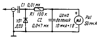
Fig.1
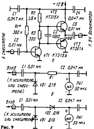
In Fig. 1 shows a diagram of the voltmeter-tester, modified in accordance with the recommendations given in [2]. It allows you to accurately measure the voltage of the local oscillator directly to the mixer diodes.
Consider simple ways of tuning and refining receivers and direct conversion transceivers, which can eliminate the above-mentioned structural defects.
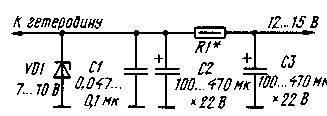
Fig.2
First of all, the revision must enter a stabilization circuit voltage of the local oscillator. The regulator circuit shown in Fig. 2. The Zener diode VD1 is chosen with a voltage stabilization in 1,5…2 times lower than the rated voltage of the receiver (transceiver). Resistor R1 sets the optimum current through the Zener diode. The resistance of the resistor R1 should be such that the current to the Zener voltage VD1 does not exceed the maximum permissible values. Capacitor C1 reduces the "leakage" of noise Zener diode, resulting in reduced noise modulation voltage of the local oscillator to reduce the overall noise of the receiver.
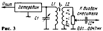
To change the RF voltage on the diodes of the mixer trimmer conveniently bezindustrialny resistor connected in parallel or in series with the coupling coil (R1 respectively in Fig. 3 and 4).
In the latter case can be used as a transformer (Fig. 4, (a) the relationship of the local oscillator with mixer tap and autotransformer (Fig. 4,6). When you fine-tune the voltage of the local oscillator (for example, when receiving signals slaboslyshascikh stations "by ear") RF voltmeter off.
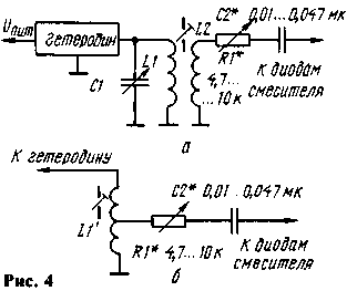
It should be noted, when using the given revision, the number of turns of the coils should slightly increase, as the results of the tuning resistor reduces the output voltage of the oscillator. This applies particularly to the embodiment, the diagram of which is shown in Fig.3. In the aggregate the number of turns of the coil connection, the resistance of the resistor R1 and the capacitance of the capacitor C2 must be such that the voltage across a silicon diode mixer can be adjusted from 0 to 1.2…2 V, for germanium, from 0 to 0.5… 1 V. In this case, the optimum voltage is reached approximately at the middle position of the slider of the resistor R1.
To regulate the output voltage of the oscillator by changing the supply voltage, as, for example, made in [3]. However, this is only true for frequencies up to 3…4 MHz. At higher (above 7 MHz) such adjustment may lead to a significant departure of the lo frequency.
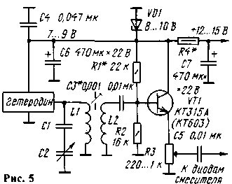
In Fig. 5 shows a diagram of a local oscillator with a buffer node that entered the circuit adjustable output voltage. When repetition is necessary to consider that the emitter follower does not amplify the voltage, and therefore the high-frequency voltage on the coil should be twice more. than required for normal operation of the mixer.
In Amateur practice, the most widely used balanced diode mixers. Their main advantages are simplicity of structure and settings, no switching at a high frequency when switching from reception to transmission. Balanced mixers on the field and bipolar transistors are used much less frequently.
In a simple balanced mixer diodes the voltage of the local oscillator and some by-products of converting the output may be suppressed by 35 dB or more. But such results are achieved only in one direction, in which the mixer is balanced. In the author's design of the transceiver [4] the mixer is balanced only in the direction of the amplifier. If you are using a double balanced mixer [5], decrease noise, increase sensitivity, improve immunity.
Double balanced mixers are balanced on both inputs (outputs). They suppress not only the fluctuations of the local oscillator, but also convert the signal, leaving only the products of their mixing and thereby ensuring the purity of the spectrum. The use of such mixers can reduce the requirements for podsystem filter connected to the output of the mixer, and even to abandon it altogether by connecting the output of the mixer directly to the if amplifier, the output of which must be the main filter selection (e.g., EMF or quartz filter). Double faucet, you can apply a much greater level signal when receiving, since it dramatically reduces the direct effect of signal detection or interference, i.e., the detection does not occur without the participation of the oscillations of the local oscillator, as is the case in conventional amplitude detector.
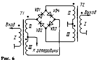
Most commonly in Amateur designs apply a double balanced mixer, the scheme of which is shown in Fig. 6. It is also called circular because the diodes included in it but the ring.
Often this mixer recommends supplementing balancing elements R1, C1, C2 (Fig. 7). Moreover, the resistor R1 should be bezindustrialny. This revision improves the parameters of the mixer.
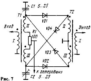
When working at low frequency bands of the high frequency transformer is wound, usually on a ferrite ring size CHH with magnetic permeability 600…1000 three twisted (3-4 twists per 1 cm length) between a wire PELSHO of 0.2. Approximately make about 25 turns (complete ring). When installing the transformer phase windings according to Fig. 6 and 7.
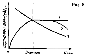
There are two main options for inclusion of the double balanced mixer in the transceiver. The first signal is output when receiving and when transmitting in one direction from input to output mixers. So, for example, made in the well-known transceivers "Radio-76" [6] and "Radio-76M2" [7]. Numerous experiments conducted by the author, revealed by heterodyne voltage that is less than optimal, significantly decreased sensitivity in receive mode, and at greater - significantly reduced the suppressed carrier transmission mode (sensitivity also decreases, but it is less noticeable on the ears than in the previous case). The qualitative dependence of the main parameters of the transceivers from the voltage level of the local oscillator input at the mixer, shown in Fig. 8 (curve 1 - reception sensitivity, determined as of the hearing, 2-sensitivity, measured by the instrument, 3 - suppression of carrier during transmission).
In the second embodiment, a signal in the reception mode is input to the balanced mixer, and when the transfer - out. With this inclusion, the principle of reversibility of the mixer. So built RF path of the transceiver described in [8]. The establishment of the mixer and in this case comes down to setting the optimal heterodyne voltage is carefully balanced. It should be particularly noted that the operation of the establishment does not depend on the principle of building radio frequency channel of the transceiver.
Now a few practical recommendations for establishing a radio frequency channel of the transceiver.
First you need to configure the mixers. Previously the engines of the balancing resistors in them set to the middle position. Next to the antenna Jack of the transceiver, connect the GSS and gradually increase the heterodyne voltage at the faucets. The signal from the GSS serves that exceed the sensitivity of the receiving path several times. It is necessary to achieve signal reception. Led generator no, the surgery is performed by ear, taking a cue Amateur radio SSB radio noise generator with a low-power Zener diode.
Then alternately adjust each of the mixers. First pick the optimal heterodyne voltage. It gradually increased and evaluate at the hearing: there is an increase in the volume of the reception of the GSS, radio station or generator noise. As noted by the author, with increasing heterodyne voltage supplied to the mixer, the volume receiving at the hearing at first increases, reaching a maximum and then remains practically unchanged (Fig. 8, curve 1). Heterodyne same voltage should be set such that the very small decrease of the volume of the reception was falling, and with its small increase did not increase. Practically this is done by moving within a narrow range of engine resistor that controls the output voltage of the oscillator. If the transceiver is not, then the device should be modified.
Typically, the output of a local oscillator included emitter follower. In this case, the refinement is very simple: constant resistor in the emitter circuit of the transistor replaced bezindustrialny trimming resistor the same value as that permanent.
After optimization of heterodyne voltage need more time to more carefully balance the faucets. To input or output (depending on the build of the transceiver) connect the RF millivoltmeter or an oscilloscope and dragging the slider of the resistor R1, and then adjusting the capacitors C1 and C2 (see Fig. 7) achieve the minimum readings. If you are using devices with high input impedance, to the input and output of the mixer should be connected close to the resistance (in the range of 50… 100 Ohm) resistors.
Preference should be given to balancing in the output side transmission path. The difference in the balance of the input and output of the mixer should be small (a few decibels). If it reaches 10 dB or more, it is usually the result of the heterodyne voltage is fed to the mixer, is much more optimal.
To check and balance mixers the author uses simple instruments. In Fig. 9, a diagram of an RF amplifier, the input of which is connected to the mixer, and the output connected to the coarse adjustment of the high-frequency voltmeter (Fig. 9, b), for fine - HF probe (Fig. 9, in). To install additional resistors 50… 100 Ohms in the mixer is not necessary.
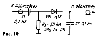
Finally faucets tune after they are installed in the transceiver (he was transferred in the transfer mode). Previously, the device should be set in receive mode. That the noise of the microphone does not interfere with the balancing, the input of the microphone amplifier short. First balance the low-frequency mixer, and then the rest in order of passage of a signal in transmission mode, while achieving a minimum readings on the HF dummy load (Fig. 10) connected to the power amplifier of the transceiver. Then adjust the settings of other nodes. This procedure it is necessary to repeat two or three times.
Literature
1. Polyakov V. T. Hams about the technique of direct conversion. - M.: Patriot, 1990, p. 264.
2. Stepanov B. Measurement of small RF voltages. Radio, 1980, vol. 7, pp. 55-56.
3. Artemenko V. Simple SSB-mini-transceiver 160 meters - Ham, 1994, No. 1.c. 45, 46.
4. Artemenko, V. A. a Simple transceiver with EMF. - Glad I oamator, 1995, No. 2, pp. 7-10.
5. Bunin S. G., Yailenko L. P. Handbook of Amateur - shortwave. - K.: Machinery, 1984, p. 264.
6. Stepanov B., G. Shulgin Transceiver Radio "-76". Radio, 1976, No. 6, pp. 17-19, vol. 7, pp. 19-22.
7. Stepanov B., G. Shulgin Transceiver "RA-dio-76M2". Radio, 1983, No. 11, pp. 21 - 23, No. 12, p. 16-18.
8. Vasiliev V. Reversible circuitry in the transceiver. Radio, No. 10, pp. 20,21.
Author: Vladislav Artemenko (UT5UDJ), Kiev. Ukraine, SW journal 4,5-97; Publication: N. Bolshakov, rf.atnn.ru