In a connected instrument is most often used double balanced mixers (DBS) for silicon diodes or diodes with Schottky barrier.
For DBS important characteristic is the degree of balancesheet, i.e. the suppressed carrier. Research conducted by the author indicate increased sensitivity and increased dynamic range in a careful balancing DBS. In this regard, the author has developed and tested a new circuit design that allows you to:
- 20 dB or more to raise the level of carrier suppression at low frequencies in the RF range (f<2 MHz);
in the balancing process to preserve the initial impedances of the ports of the mixer, including when a significant change in carrier frequency (within 0.1...30 MHz or more).
The application of the proposed circuit solution allows to increase the sensitivity and dynamic range in the receive mode.
Consider the balancing process mixers of the transceiver in more detail. The basic scheme of DBS is presented in Fig. 1. This scheme does not contain additional elements balancing and thus of nonidentity in the characteristics of diodes, as a rule, does not allow the carrier suppression more than 30 dB even at frequencies below 10 MHz. At frequencies above 10 MHz carrier suppression decreases. However, the carrier suppression 30 dB is sufficient.
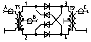
Fig.1
In Fig.2 is a diagram of a DBS with a balancing capacitors. The connection point of the capacitors is determined empirically for maximum carrier suppression. Thus it is possible to suppress the carrier 40...50 dB. Such values of the carrier suppression is already acceptable for communication equipment.
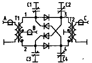
Fig.2
However, this scheme does not allow a good balance mixer at sufficiently low frequencies (0.5 to 2 MHz). To eliminate this drawback schemes introduce additional balancing balancing resistor (Fig.3). But this scheme has drawbacks. The most significant of them - a significant change in input resistance mixer with the introduction of the balancing resistor. So the change of resistance of the mixer was minimal, you must use asyndetically the low-impedance resistor.
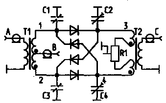
Fig.3
The author proposes a new simple method for balancing based on the method of replacement [2]. Scheme (Fig.4) combines the advantages of the above diagrams (Fig.2 and 3). This gives a good opportunity to balance the faucets on all frequencies. In this case, the balancing resistance changes significantly smaller than in the circuit of Fig.3. Of the capacitors and the resistors select empirically. However, this scheme does not eliminate the deterioration of the balance mixer with a significant change in carrier frequency, for example in the first mixer multi-band transceiver.
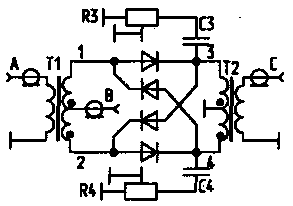
Fig.4
For maximum and uniform carrier suppression if you change the carrier frequency in a very wide range are introduced into the mixer switched when changing ranges of the balancing elements. A variant of this scheme is presented in Fig.5.
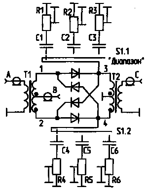
Fig.5
This requires switching to the RF, which is a disadvantage. This defect free scheme presented in Fig.6.
Scheme of Fig.6 allows to produce and maintain a high degree of balancing DBS, even with the restructuring of the carrier frequency within the entire SW range.
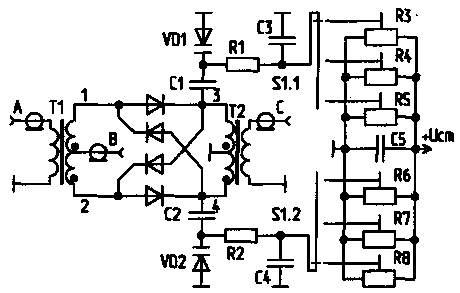
Fig.6
Proposed schematic DBS well-established in the design of multi-band transceiver of the author.
Literature
1. Artemenko V. methods of establishing receivers and direct conversion transceivers/ glad I oamator. - 1995. - N6. - S. 24 - 25.
2. Baghdasaryan G. On the frequency tuning LC-generator/ Radio. 1994 No. 7, C. 37.
Author: V. Artemenko (UT5UDJ), Kyiv; Publication: N. Bolshakov, rf.atnn.ru


