This time the circuitry of the mixer on electronic keys and a few practical schemes. Say something like this already, but not for nothing they say: "repetition is the mother of learning". They learn young hams on the principle of operation of the mixer. if the old magazines in the trash, and new literature is only about computers? Meanwhile the circuitry of the mixer is continuously improved. The developers aim to get a mixer with ideal settings: wide dynamic range. simple, economical, technological, and broadband. Therefore, it may be an assembled mixer on high-speed keys-driven high-speed CMOS digital circuits.
The radio has not diminished interest in the circuitry of the mixer. Modern element base allows you to design unusual faucets with amazing properties. But first a bit of theory and terminology. In the Amateur radio environment, there is a division of faucets for the key and "smooth" - in appearance of the lo signal, rectangular or sinusoidal. Also talk about passive and active mixers, passive mixers unlike active not amplify the converted signal.
The principle of operation, collectively, all faucets are switch the phase of the input signal with the frequency of the lo signal. As switching elements are commonly used diodes, transistors or electronic switches. Moreover, active, of course, can be faucets only transistors. Although NS all transistor mixers are active. For example, the mixer, causing a great readers ' interest and considered in RD No. 1-97 on page 11, is not active.
The principle of operation of the mixer is easy to understand, considering the scheme of the classic diode ring balanced mixer, Fig.1.
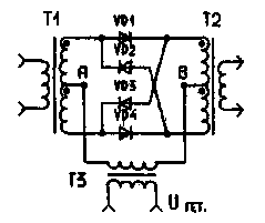
Figure 1. Ring balanced mixer diodes
The voltage of the local oscillator Uгет. at the moment when its polarity at point a relative to point In a positive, opens a couple of diodes VD1 and VD4. In case of occurrence of a signal, it passes from input to output of the mixer through these diodes. This continues until, until the voltage of the local oscillator will not change their sign. In this case, the diodes VD1, VD4 close and diodes VD2, VD3 open. Through these diodes passes the same signal as in the first case, only the phase at the output of the mixer is changed to a reverse - start to run the opposite terminals of the secondary winding of transformer T2. Currents in a symmetrical local oscillator windings of transformers T1 and T2 at any time from opposite directions and vzaimounichtozhaem. Of course, without special measures, to achieve the reasonable compensation of these currents is difficult, and at the mixer output appears the remainder of the signal with the frequency of the local oscillator (carrier). For the balanced mixer in the gap of one of the symmetrical transformer windings is switched variable resistor. But deep suppression of the carrier and in this case it is difficult to achieve - here affected by technological variations of the resistances of the diodes, the asymmetry of the windings of transformers, circuit capacity, and other factors.
Now imagine that the diodes we have replaced the electronic key switches, with properties close to conventional relay contacts, but with much more speed, Fig.2.
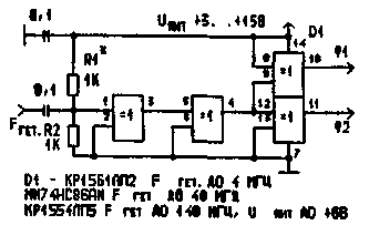
Fig 2 Ring balanced mixer in the keys
In this case, the control circuit and the circuit of the signal are separated, which significantly reduces their mutual penetration. But that's not all the benefits. Modern electronic switches ( for example MAH firm MAXIM) have the on-state resistance less than 2 Ohms and switching speed of about 100 nanoseconds. Moreover, the parameters of each of the four keys in the chip package, save in the range of the dial-up voltage in the range +/-20 V. This means that the public key absolutely does not introduce harmonic distortion in the pass-through signal.
Electronic switches are controlled by digital signals with the levels applied to the findings of "F1" and "F2" in opposite phase from IC driver lo signal. The generator circuit is shown in Fig.3.
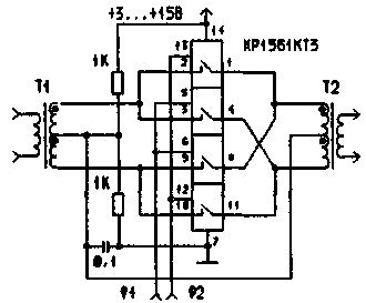
Figure 3 signal Generator key management
The input impedance is determined by the value of the resistors R1, R2, and amplitude applied to the input lo signal is approximately equal to 0.5 V. the Weakening of through-penetration control signal to circuit switched according to the specifications on the chip series 1561 exceeds the sum of (-130 dB in the mixer, assembled on such keys without much difficulty to achieve carrier suppression to almost 100 dB!
I have tested more circuits mixers that were used as trainers DSB signal as mixers and vectors at the operating frequency when operating at low frequency LW bands from 160 to 40 meters. In the simplest scheme uses only one key. In Fig.4 shows the schematic of this mixer. It is used as a DSB-shaper.
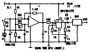
Fig.4 the Mixer on one key
The microphone amplifier is any operational amplifier. The source signal is supplied to it with electret condenser microphone. The input key is connected directly with the output of "operacionnie", and the circuit R1, R2, C1 automatically maintain the balanced mixer. The resonance properties of the Electromechanical filter restores the horizontal symmetry of the output signal. The advantage of this scheme is its simplicity and the fact that the control signal is a unipolar signal with the frequency of the local oscillator. When using miniature piezoelectric EMF type FEM-031 -500-3,1 IN-2, the capacitor C2 can be deleted, and the resistors Rl and R2 to pick up for negotiation mixer with an input impedance of the filter, which in this case would be about 5 ohms.
Following the balanced modulator, Fig.5 works well at frequencies up to 12 MHz, but unlike the previous mixer, this also requires control of vapour phase.
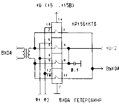
Figure 5 Balanced mixer with two keys
As the transformer T1 is used matching the LF transformer of the receiver, and for those who are allergic to the transformers, we can recommend the scheme of Fig.6.
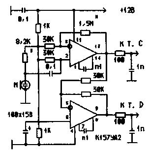
Figure 6 Microphone amplifier with vapour phase output
When the frequency of the local oscillator 500 kHz carrier suppression in this scheme was 94 dB. This scheme was successfully used as the second mixer - carrier on the range, and also as demodulator or SSB detector, Fig.7.
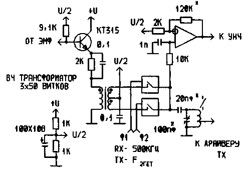
Fig 7 the Second mixer-demodulator
On the basis of these nodes I have was assembled and operated for several years, small-sized bass compressor, which allowed me to forget that this swapping of the output stages of transmitters. Its simplified schematic is shown in Fig.8.
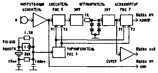
Fig.8 HF compressor with key faucets
Idea .this device has long been known, but, judging by the publications, still resonate in ham radio in the form of one or another of the technical implementation. The principle of operation is to limit the generated SSB signal, then filtering it on the extra EMF. The proposed circuitry mixers allows to obtain a linear signal. Thus, when the degree of limitation of about 15 dB correspondents on the air did not notice the appearance of noticeable distortion, usually related to compression, but noted an increase in the level of the signal at 1.5 points.
The linearity of the tract due to the lack of distortion in mixers. Due to the relatively higher level signals and low currents in the order of the scheme, no need for shielding of its parts, and the carrier suppression is achieved with a completely random installation. The compressor has three outputs, which facilitates experimentation with it. To the first output will yield a linear NS compressioni the signal from the microphone amplifier. The second low-frequency compressively signal. And on the third output - SSB compressing the signal.
The entire device fits in the housing of the handheld microphone of the portable transceiver. Current consumption from the source 12 is about 15 mA. One time I used this microphone as a single-band shaper for transmitting the STB to the receiver with one transformation. Added only the second mixer, Fig.7, the push-pull driver, whose scheme is shown in R-D No. 1-97 on page 15, and power amplifier (R-D No. 2-97, p. 3). Turned out small, but powerful "thing to give". In future it is proposed to experiment with the keys in the transceiver mixers consoles to more complex receivers, as well as to the direct conversion transceivers.
In Fig.9 is a diagram of another mixer. He used me as the first mixer of the transmitter with a set of filters "Quartz 35" and is good because it does not require output mid-point of the transformer.
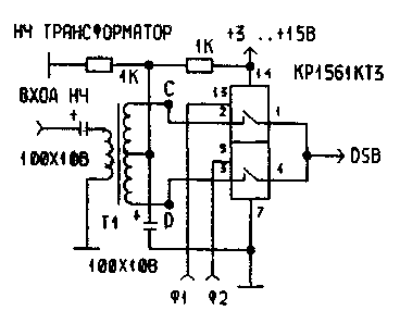
Fig.9 the Mixer on the keys with a simple transformer
I want to reiterate that the above scheme was tested by me only in paths of signal transmitters for low-frequency Amateur bands. Using the keys on top LW ranges is hampered by the lack of information about faster chips. I will be grateful hams who provided the information.
As to the application of this circuitry in the receiver, this is a topic for further experiments In my opinion, quite possibly the use of such mixers, for example, as SSB detectors. And high-speed keys can be used in the first mixer of the receiver. Imagine what they will have dynamic range when they are able to switch without distortion dvadtsatipostovoy signal!
Author: S. Makarkin, RX3AKT; Publication: N. Bolshakov, rf.atnn.ru


